Tensioner

A technology for tensioning devices and shaft components, applied to transmission devices, belts/chains/gears, mechanical equipment, etc., to achieve the effects of suppressing amplitude, reducing output loss, and increasing frictional torque

Inactive Publication Date: 2005-04-13
NHK SPRING CO LTD
View PDF1 Cites 2 Cited by
  • Summary
  • Abstract
  • Description
  • Claims
  • Application Information

AI Technical Summary

Problems solved by technology

[0015] Even according to the construction of No.2001-21012, the amplitude of the drive shaft can be controlled, but the amplitude control of this construction can only be used for certain types of engines

Method used


Image

  • Tensioner
  • Tensioner
  • Tensioner

Examples


Embodiment 1

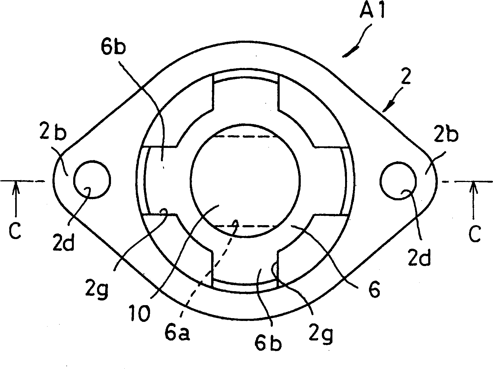
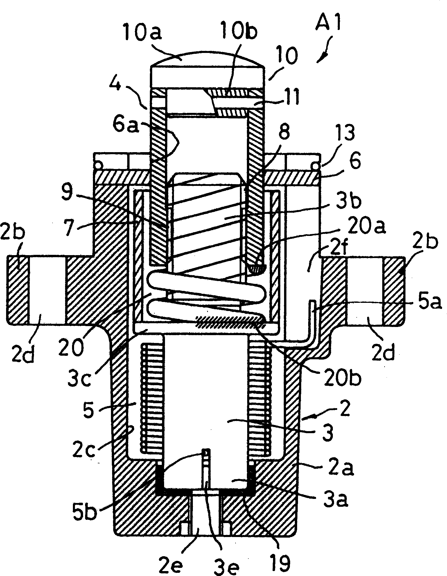
[0057] Figure 1 ~ Figure 3 A tensioner A1 according to Embodiment 1 of the present invention is shown, which includes a housing 2 , a first shaft member 3 , a second shaft member 4 , a torsion spring 5 , a bearing 6 , and a spacer 7 .

[0058] The housing 2 is substantially T-shaped in cross section, and its flange portion 2b extends from the top end of the trunk portion 2a in a direction substantially perpendicular to the driving direction. Also, an accommodation hole 2c is formed extending in the axial direction (driving direction) from the trunk portion 2a to the flange portion 2b. The top end portion of the housing hole 2c is open, and an assembly of the first and second shaft members 3, 4, the torsion spring 5, and the partition plate 7 is placed in the housing hole 2c.

[0059] The flange part 2b of the housing 2 is used to connect with the engine body of the equipment used, and a mounting hole 2d is formed in the flange part 2b, through which a bolt (not shown) is scr...

Embodiment 2

[0078] Figure 4 A tensioner A2 according to the second embodiment of the present invention is shown, and a buffer plate 22 is inserted between the coil spring 20 constituted by a compression spring and the flange portion 3c of the first shaft member 3 . The buffer plate 22 is made of a thin metal plate such as a washer, and is sandwiched between the other end portion 20 b of the coil spring 20 and the flange portion 3 c of the first shaft member 3 .

[0079] By providing such a buffer plate 22 , it is possible to prevent the other end portion 20 b of the coil spring 20 from biting into the first shaft member 3 . This enables smooth operation of the coil spring 20, suppresses abrasion of the coil spring 20 and the first shaft member 3, and improves durability of the tensioner.

[0080] Figure 5 and Figure 6 A variant of this embodiment is shown. exist Figure 5 In this way, between the flange portion 3c of the first shaft member 3 and the other end portion 20b of the co...

Embodiment 3

[0084] Figure 7 A tensioner A3 according to Example 3 of the present invention is shown. In the tensioner A3 of this embodiment, both end portions 20a, 20b of the coil spring 20 constituted by a compression spring are supported by the first shaft member 3 and the second shaft member 4 .

[0085] That is, between the flange portion 3c and the threaded portion 3b of the first shaft member 3, a raised portion 3g having an outer diameter corresponding to the inner diameter of the coil spring 20 is formed. On one side of the shaft member 3 is formed a shoulder protrusion 4g having an outer diameter corresponding to the inner diameter of the coil spring 20 . These convex portions 3 g , 4 g are support seats that support the ends of the coil spring 20 . Furthermore, by inserting these protrusions 3g, 4g into both end portions 20a, 20b of the coil spring 20, a more stable support state can be maintained. Furthermore, a metal washer 22 serving as a buffer plate is sandwiched betwee...


PUM


Abstract

A tensioner that can precisely control the vibration amplitude of the second shaft member of the tensioner to which an external input load is applied. In the present invention, the first shaft member (3) and the second shaft member (4) screwed together by the threaded parts (8, 9) and the torsion spring (5) rotating in one direction and compressing the first shaft member (3) Contained in the housing (2). The rotational momentum of the torsion spring (5) is converted into the driving force of the second shaft member (4), and the rotation of the second shaft member (4) is restricted. An elastic member (20) is provided between the first shaft member (3) and the second shaft member (4) to generate a resisting torque corresponding to an external input load applied to the second shaft member (4), thereby precisely suppressing the second shaft member (4). Amplitude of the 2-axis component (4).

Description

technical field [0001] The invention relates to a tensioning device for maintaining a certain tension in an endless belt or chain. Background technique [0002] A tensioning device, which is pressed with a predetermined force such as a timing chain or a timing belt used in an automobile engine, has the function of maintaining a certain tension when it is stretched or relaxed. [0003] Figure 13 A state in which the tensioner 100 is attached to an automobile engine block 200 is shown. A pair of camshaft sprockets 210 , 210 and a crankshaft sprocket 220 are arranged inside the engine block 200 , and an endless timing chain 230 is wound around these sprockets 210 , 210 , 220 . In addition, a freely movable chain guide groove 240 is arranged on a moving path of the timing chain 230 , and the timing chain 230 can slide on the surface of the chain guide groove 240 . A positioning portion 250 is formed on the engine body 200 , and the tensioning device 100 is fixed on the positi...

Claims


Application Information

Patent Timeline
Patent Type & Authority Applications(China)
IPC IPC(8): F16H7/08
CPCF16H7/0848F16H2007/081F16H2007/0853F16H2007/0857
Inventor 天野种平小林贵雄
Owner NHK SPRING CO LTD
Why Eureka
Try Eureka