A Charge Pump Structure

A charge pump, potential technology, applied in electrical components, high-efficiency power electronic conversion, output power conversion devices, etc., can solve the problems of reducing the occupied area and low efficiency, reducing the occupied area, reducing costs, and avoiding collusion effect of the phenomenon

Active Publication Date: 2019-12-27
UNIV OF ELECTRONICS SCI & TECH OF CHINA
View PDF1 Cites 0 Cited by
  • Summary
  • Abstract
  • Description
  • Claims
  • Application Information

AI Technical Summary

Problems solved by technology

[0004] In view of the low efficiency caused by collusion in the above-mentioned traditional cross-coupled charge pump, the present invention proposes a charge pump structure based on the cross-coupled charge pump model, which is used to improve the efficiency of the charge pump and can solve the above-mentioned shortcomings of the traditional charge pump , effectively avoiding the collusion phenomenon, eliminating the threshold loss caused by the body effect, and improving the charging efficiency of the charge pump; at the same time, the level conversion unit is used, so that the charge pump unit can achieve high-level output with only a single stage, effectively Reduced footprint and reduced costs

Method used


Image

  • A Charge Pump Structure
  • A Charge Pump Structure
  • A Charge Pump Structure

Examples


Embodiment Construction

[0037] Below in conjunction with accompanying drawing and specific embodiment, describe technical solution of the present invention in detail:

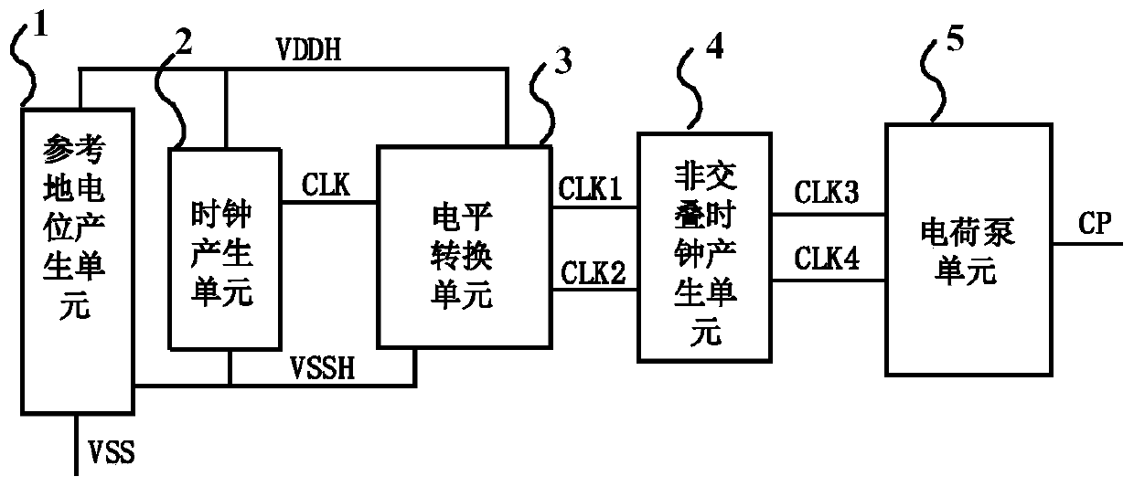
[0038] A charge pump structure proposed in the present invention is based on a cross-coupled charge pump model, and uses non-overlapping clocks and substrate selection to control the gate and substrate potentials of the switching tubes, effectively avoiding the occurrence of collusion and eliminating bulk The threshold loss caused by the effect improves the charging efficiency of the charge pump. Such as figure 1Shown is the overall block diagram of the charge pump structure proposed by the present invention, including a reference ground potential generation unit 1, a level conversion unit 3, a non-overlapping clock generation unit 4 and a charge pump unit 5, and the reference ground potential generation unit 1 is used to generate Reference ground potential VSSH, its power supply voltage is high level VDDH, and its ground voltage is...


PUM


Abstract

A charge pump structure belongs to the technical field of electronic circuits. Including a reference ground potential generation unit, a level conversion unit, a non-overlapping clock generation unit and a charge pump unit, the reference ground potential generation unit is used to generate a reference ground potential, its power supply voltage is high level, and its ground voltage is low level ; The level conversion unit is used to generate the first overlapping clock signal and the second overlapping clock signal, the control signal of which is a clock control signal, the power supply voltage is a high level, and the ground voltage is a reference ground potential; the non-overlapping clock signal is generated The unit is used to convert the first overlapping clock signal and the second overlapping clock signal into the first non-overlapping clock signal and the second non-overlapping clock signal; the power supply voltage of the charge pump unit 5 is high level, and the ground voltage is Low level, under the control of the first non-overlapping clock signal and the second non-overlapping clock signal, the high level is pumped up to generate the output signal of the charge pump structure. The invention improves the charging efficiency of the charge pump and reduces the occupied area.

Description

technical field [0001] The invention belongs to the technical field of electronic circuits and relates to a charge pump structure. Background technique [0002] At this stage, with the widespread use of memory, the writing and erasing of data requires an operating voltage much higher than the power supply voltage, so a charge pump can be used to pump up a lower power supply voltage to obtain a high operating voltage, while the traditional crossover The coupled charge pump has efficiency loss due to the existence of collusion phenomenon and cascaded charge pumps. The collusion phenomenon is that the branch circuit leakage phenomenon occurs in the charge pump during the turn-on and turn-off process of the MOS transistor. [0003] Traditional cross-coupled charge pump structures such as figure 2 As shown in the middle charge pump unit 5, the generation of the cross-talk phenomenon is related to the boost transistors (MN4, MN5) and switch transistors (MP10, MP11) in the charge ...

Claims


Application Information

Patent Timeline
Patent Type & Authority Patents(China)
IPC IPC(8): H02M3/07H02M1/38
CPCH02M1/38H02M3/07H02M1/0048Y02B70/10
Inventor 李泽宏张成发孙河山赵念熊涵风
Owner UNIV OF ELECTRONICS SCI & TECH OF CHINA
Why Eureka
Try Eureka