A conveying mechanism of roller inner hole oiler

A conveying mechanism and inner hole technology, applied in the field of roller inner hole oiler and roller inner hole oiler conveying mechanism, can solve the problem of low efficiency, inability to ensure that the inner hole of the bearing is cleaned, and inability to ensure that the grease is evenly applied to the surface. Problems such as the hole wall of the inner hole of the roller

Active Publication Date: 2020-05-19
临沭县济才人力资源服务有限公司
View PDF8 Cites 0 Cited by
  • Summary
  • Abstract
  • Description
  • Claims
  • Application Information

AI Technical Summary

Problems solved by technology

[0003] At present, the oiling process of the roller is mainly carried out manually. The workers now clean the inner hole of the bearing, and then apply the grease to the inner hole of the roller through an oiling stick; the efficiency of manual oiling is low. At the same time, it is impossible to ensure that the inner hole of the bearing is scrubbed clean, and it is also impossible to ensure that the grease is evenly applied to the wall of the inner hole of the roller.

Method used


Image

  • A conveying mechanism of roller inner hole oiler
  • A conveying mechanism of roller inner hole oiler
  • A conveying mechanism of roller inner hole oiler

Examples


Embodiment Construction

[0020] The following are specific embodiments of the present invention and in conjunction with the accompanying drawings, the technical solutions of the present invention are further described, but the present invention is not limited to these embodiments.

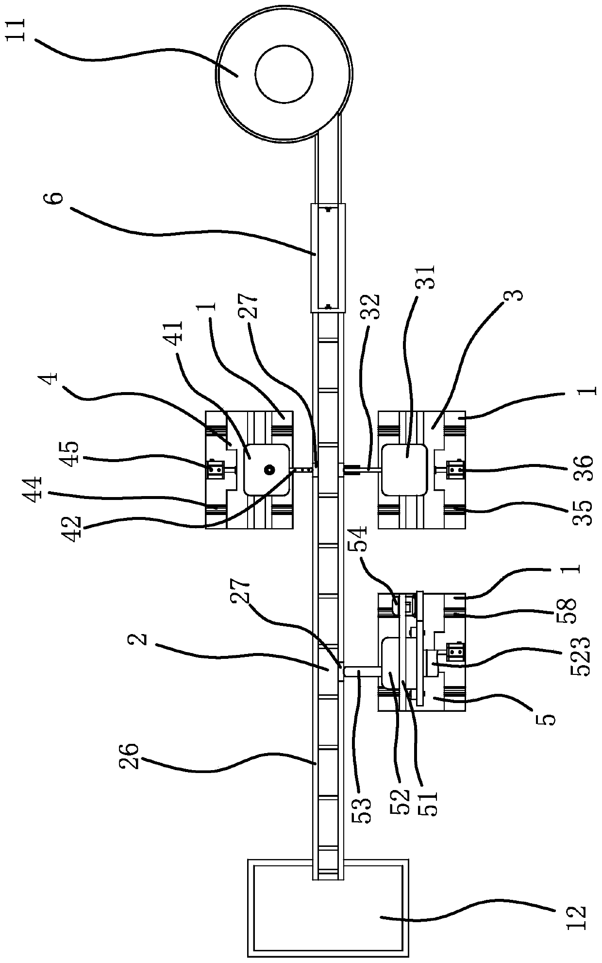
[0021] like Figure 1 to Figure 6 As shown, the roller inner hole oiler includes a frame 1, one end of the frame 1 is fixed with a vibrating feeding tray 11, and the other end of the frame 1 is fixed with a receiving box 12.

[0022] The conveying mechanism includes a conveyor belt 2 and a guide wheel tube 6 capable of vertically positioning and conveying the rollers. The beginning of the conveyor belt 2 is located directly below the discharge opening of the vibrating feeding tray 11, and the end of the conveyor belt 2 is located directly above the receiving box 12. The guide wheel tube 6 is vertically arranged between the feeding port of the vibrating feeding tray 11 and the conveyor belt 2, and the upper end of the guidi...


PUM


Abstract

The invention provides a conveying mechanism of an oiling machine for rolling wheel inner holes and belongs to the technical field of machinery. The conveying mechanism solves the technical problems of low oiling efficiency of existing rolling wheel inner holes and the like. The oiling machine for the rolling wheel inner holes comprises a frame. One end of the frame is fixedly provided with a vibrating feeding tray. The other end of the frame is fixedly provided with a material receiving bin. The conveying mechanism comprises a conveying belt and a wheel-guiding pipe. The beginning terminal ofthe conveying belt is right below a feeding inlet of the vibrating feeding tray. The tail end of the conveying belt is right above the material receiving bin. The wheel-guiding pipe is vertically arranged between the feeding inlet and the conveying belt. A material inlet is formed in the upper end of the wheel-guiding pipe and communicates with the feeding inlet of the vibrating feeding tray. A material outlet is formed in the lower end of the wheel-guiding pipe. The material outlet faces the tail end of the conveying belt. Two opposite inner walls of the wheel-guiding pipe are provided withdamping baffles which can slow down the falling of the rolling wheel. The wheel-guiding pipe is provided with a plurality of damping baffles in the vertical direction. The conveying mechanism has theadvantages of improving the oiling efficiency of the rolling wheel inner holes.

Description

technical field [0001] The invention belongs to the technical field of machinery, and relates to a roller inner hole oiler, in particular to a conveying mechanism of a roller inner hole oiler. Background technique [0002] Products such as trolley cases and trolley schoolbags are equipped with rollers for easy movement. The rollers are generally connected to the body of the trolley case or the trolley schoolbag through a shaft. Bearings are installed between the rollers and the shaft to reduce rotational noise. The inner hole of the roller is oiled, and then the subsequent assembly is completed. [0003] At present, the oiling process of the roller is mainly carried out manually. The workers now clean the inner hole of the bearing, and then apply the grease to the inner hole of the roller through an oiling stick; the efficiency of manual oiling is low. At the same time, it cannot be guaranteed that the inner hole of the bearing is scrubbed clean, nor can it be guaranteed th...

Claims


Application Information

Patent Timeline
Patent Type & Authority Patents(China)
IPC IPC(8): B05C7/06B05C13/02B08B1/02B08B5/02
CPCB05C7/06B05C13/02B08B1/002B08B1/02B08B5/023
Inventor 韩菲菲
Owner 临沭县济才人力资源服务有限公司
Why Eureka
Try Eureka