Automatic feeding and discharging device for steel tube cutting

An automatic technology for feeding and discharging materials, applied in the direction of shearing devices, shearing machine accessories, metal processing equipment, etc., can solve the problems of reducing production efficiency, steel pipe collision, physical exertion, etc., to improve production efficiency, protect steel pipes, and avoid The effect of falling directly

Inactive Publication Date: 2018-09-21
高婷婷
View PDF10 Cites 8 Cited by
  • Summary
  • Abstract
  • Description
  • Claims
  • Application Information

AI Technical Summary

Problems solved by technology

[0003] Generally, steel pipes need to be processed on-site at the work site, so large-scale factory processing equipment cannot be used. The traditional steel pipe cutting process requires manual participation. Pushing and feeding the steel pipes not only consumes a lot of physical strength, but also the operation is not continuous, which reduces production. In addition, at the discharge end, the free fall of the steel pipes after cutting will cause the steel pipes to collide with each other, causing damage to the paint surface and requiring re-stacking; therefore, a simple structure, easy to control and able to overcome manual feeding and discharging is required. Defective steel pipe inlet and outlet device

Method used


Image

  • Automatic feeding and discharging device for steel tube cutting
  • Automatic feeding and discharging device for steel tube cutting
  • Automatic feeding and discharging device for steel tube cutting

Examples


Embodiment Construction

[0019] The following will clearly and completely describe the technical solutions in the embodiments of the present invention with reference to the accompanying drawings in the embodiments of the present invention. Obviously, the described embodiments are only some, not all, embodiments of the present invention. Based on the embodiments of the present invention, all other embodiments obtained by persons of ordinary skill in the art without making creative efforts belong to the protection scope of the present invention.

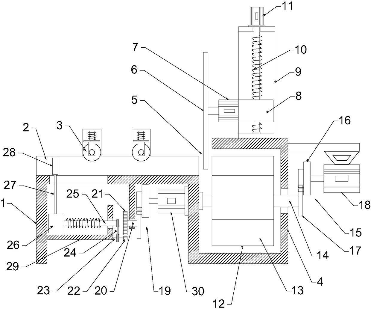
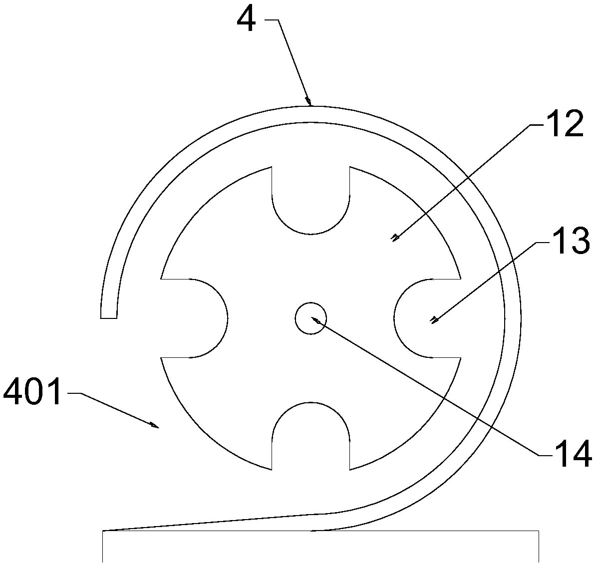
[0020] see figure 1 , in an embodiment of the present invention, an automatic feeding and discharging device for steel pipe cutting includes a feeding frame 1 and a discharging barrel 4; the upper end of the feeding frame 1 is provided with a feeding groove 2, and the feeding groove 2 is a U-shaped concave Squeeze roller 3 is arranged above the feed trough 2, and the squeeze roller 3 squeezes and fixes the steel pipe; the right side of the feed frame 1 is conn...


PUM


Abstract

The invention discloses an automatic feeding and discharging device for steel tube cutting. The device comprises a feeding frame and a discharging cylinder; a feeding groove is formed in the upper endof the feeding frame, and a squeezing roller is arranged above the feeding groove; the discharging cylinder is connected to the right side of the feeding frame, and a cutting groove is formed in thejunction between the feeding frame and the discharging cylinder; a cutting wheel is arranged above the cutting groove, and the cutting wheel is connected with a cutting motor through an output shaft.By arranging a pushing disk driven by a screw rod and a Maltese crossmovement connected with the screw rod, the pushing disk is driven to push steel tubes for intermittent feeding, and by arranging arotary frame, the discharging cylinder and a drive mechanism connected with the Maltese cross movement, intermittent blanking is achieved, it can be avoided that the steel tubes directly fall, and thesteel tubes are protected; through intermittentfeeding and discharging mechanisms which are composed by two Maltese cross movements, feeding and discharging cooperation is achieved, compared with theartificial feeding and discharging, seamless connection of the feeding and discharging is achieved, and the production efficiency is greatly improved.

Description

technical field [0001] The invention relates to the field of cutting, in particular to an automatic feeding and discharging device for steel pipe cutting. Background technique [0002] Steel pipes are widely used in various fields. Steel pipes are not only used to transport fluids and powdery solids, exchange heat, and manufacture mechanical parts and containers. It is also an economical steel. Using steel pipes to manufacture building structure grids, pillars and mechanical supports can reduce weight, save 20-40% of metal, and realize factory-like mechanized construction. The use of steel pipes to manufacture highway bridges can not only save steel and simplify construction, but also greatly reduce the area of ​​the protective layer, saving investment and maintenance costs. [0003] Generally, steel pipes need to be processed on-site at the work site, so large-scale factory processing equipment cannot be used. The traditional steel pipe cutting process requires manual part...

Claims


Application Information

Patent Timeline
IPC IPC(8): B23D33/02B23D33/00
CPCB23D33/02B23D33/00
Inventor 高婷婷
Owner 高婷婷
Why Eureka
Try Eureka