Plate cutting device

A cutting device and plate technology, applied in the field of plate processing, can solve the problems of low processing efficiency, excessive sawdust, and complexity, and achieve the effect of fast processing, stable and fast cutting

Active Publication Date: 2018-09-21
SHENZHEN LOTUT INNOVATION DESIGN CO LTD
View PDF4 Cites 1 Cited by
  • Summary
  • Abstract
  • Description
  • Claims
  • Application Information

AI Technical Summary

Problems solved by technology

[0003] However, when using the second method to process block wood, it is necessary to carry out grinding dust processing on the surface of block wood many times, the process is very complicated, and the processing efficiency is low; causing a lot of wood to be wasted

Method used


Image

  • Plate cutting device
  • Plate cutting device
  • Plate cutting device

Examples


Embodiment Construction

[0019] Further detailed explanation through specific implementation mode below:

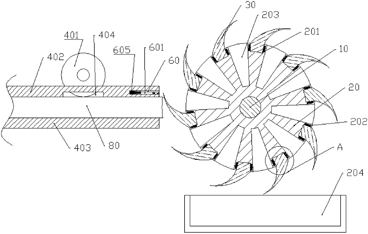
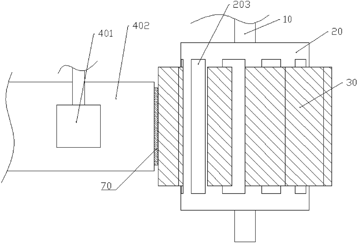
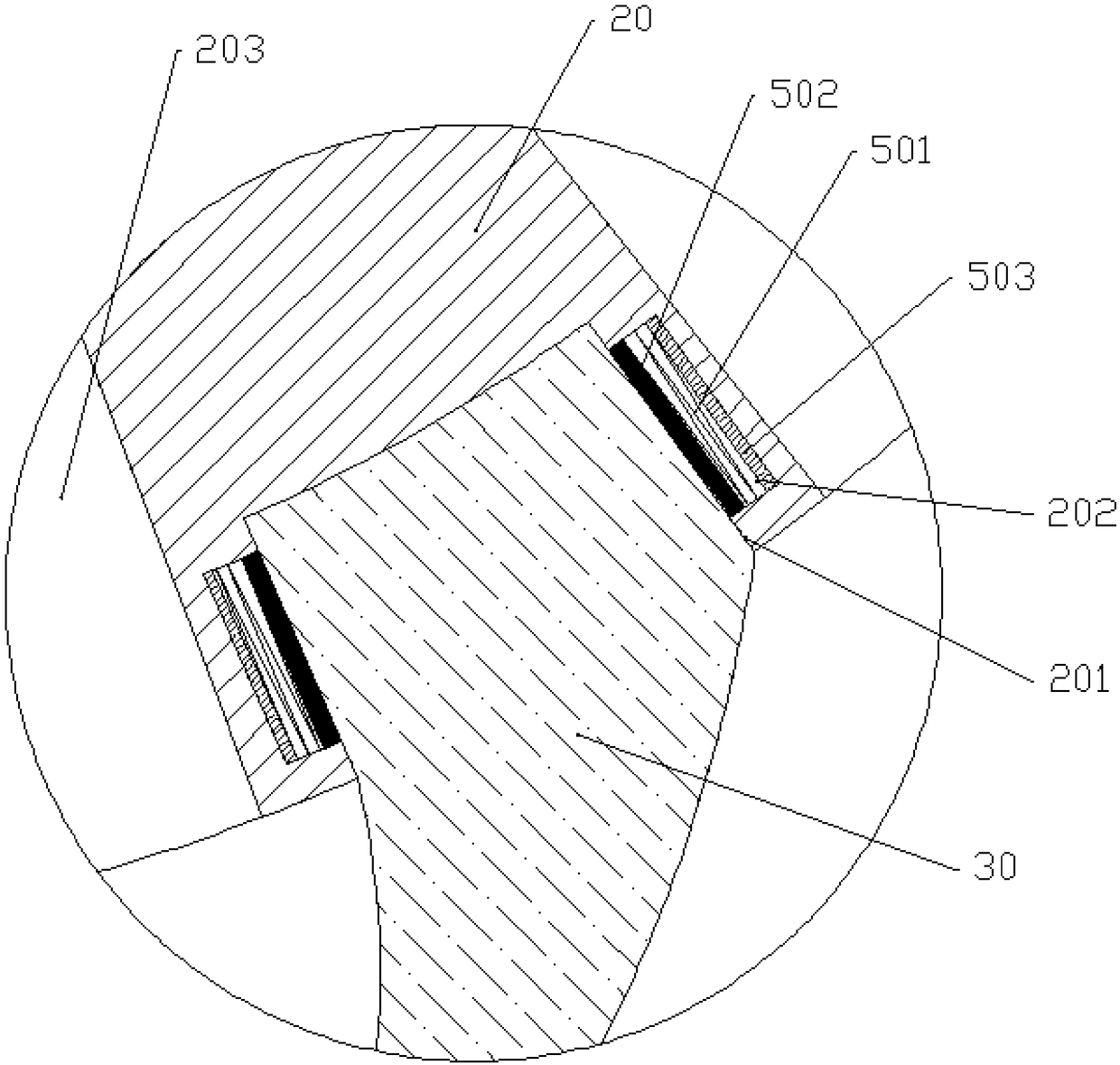
[0020] The reference numerals in the accompanying drawings of the specification include: the rotating shaft 10, the cutting roller 20, the installation groove 201, the first groove 202, the receiving groove 203, the collecting groove 204, the cutter 30, the conveying roller 401, the conveying plate 402, the fixing plate 403, Through slot 404, first compression spring 501, locking block 502, first electromagnet 503, second groove 60, first rod 601, second rod 602, contact sensor 603, second compression spring 604, second electromagnetic Iron 605, plate 70.

[0021] The embodiment is basically as attached figure 1 , attached figure 2 And attached image 3 Shown: Plate cutting device, including cutting mechanism, conveying mechanism, limit unit and ten disassembly units.

[0022] The cutting mechanism includes a cutting roller 20, a horizontally arranged rotating shaft 10 and ten cutters 30. Th...


PUM


Abstract

The invention relates to the field of plate machining, and discloses a plate cutting device which comprises a cutting mechanism and a conveying mechanism. The cutting mechanism comprises a cutting roller, a rotary rotating shaft and a cutter. The cutter comprises an installation portion and a cutter portion, the side face of the cutting roller is provided with an installation groove, the installation portion and the installation groove are detachably connected, the cutting roller is coaxially and fixedly installed on the rotating shaft, a cutting edge of the cutter portion is in a horizontal straight line shape, the straight line is parallel to the axis of the rotating shaft, and the length of the straight line is larger than the wood width. The conveying mechanism comprises a conveying roller, a conveying plate and a fixing plate which are sequentially arranged from top to bottom. The conveying plate is provided with a through groove allowing the conveying roller to penetrate therein,the side face of the conveying roller can abut against the upper surface of wood, the conveying plate and the fixing plate are both horizontally and fixedly arranged, a gap for containing the plate is arranged between the conveying plate and the fixing plate, and one side of the conveying plate and the fixing plate is opposite to the side face of the cutter roller. By means of the scheme, wood waste caused in the arc plate machining process can be reduced.

Description

technical field [0001] The invention belongs to the field of plate processing, and in particular relates to a plate cutting device. Background technique [0002] Arc-shaped panels are generally manufactured in two ways. The first is to use multiple wooden strips or wood chips to press into an arc shape. The second is to use wood raw materials for cutting and grinding. The wood raw materials need to be cut first. into a block, and then grind or cut the block of wood to make the side of the wood a curved surface; the strength of the curved plate formed by the first method is too low to be used for load-bearing; while the second method The curved plate processed by this method has high strength and is not easy to be damaged in the high-strength use environment. [0003] However, when using the second method to process blocky wood, it is necessary to perform multiple abrasive processing on the surface of the blocky wood. The process is very complicated and the processing effici...

Claims


Application Information

Patent Timeline
Patent Type & Authority Applications(China)
IPC IPC(8): B27B5/12B27B5/06B27B5/29B27B31/08B27B25/02
CPCB27B5/06B27B5/12B27B5/29B27B25/02B27B31/08
Inventor 曾雨琳詹华山李涛黄诗鸿张小恒袁苗达
Owner SHENZHEN LOTUT INNOVATION DESIGN CO LTD
Why Eureka
Try Eureka