
a hoisting tool

A tooling and hoisting technology, which is applied in hoisting devices, portable lifting devices, etc., can solve the problems of cost increase, production operation overlap, and low efficiency, and achieve the effects of simple structure, convenient operation, and low manufacturing cost

Active Publication Date: 2020-02-07
CHERY AUTOMOBILE CO LTD
View PDF3 Cites 0 Cited by
  • Summary
  • Abstract
  • Description
  • Claims
  • Application Information

AI Technical Summary

Problems solved by technology

[0002] In the whole vehicle manufacturing process, it is often necessary to hoist, transfer and store heavier sub-assemblies; some stations cannot use traditional hoists and other spreaders due to reasons such as location and production requirements, and using cantilever cranes or forklifts will greatly Increase the cost, and there are still many problems such as crossover of production operations, storage and transshipment; and purely manual hoisting is too heavy, inefficient, and has potential safety hazards. In this way, a suitable and flexible hoisting auxiliary structure is needed to assist manual hoisting. Reduce the labor intensity of operators and improve hoisting efficiency

Method used


Image

  • a hoisting tool
  • a hoisting tool
  • a hoisting tool

Examples


Embodiment 1

[0026] This embodiment proposes a hoisting tool applied to an automobile assembly workshop for transfer and auxiliary assembly of components at different stations.

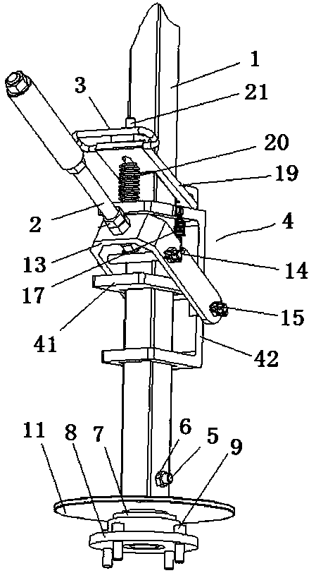
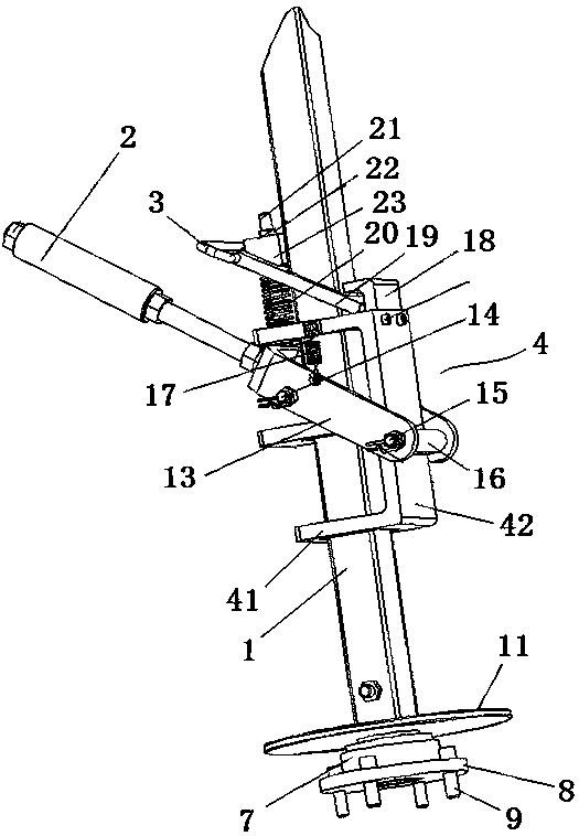
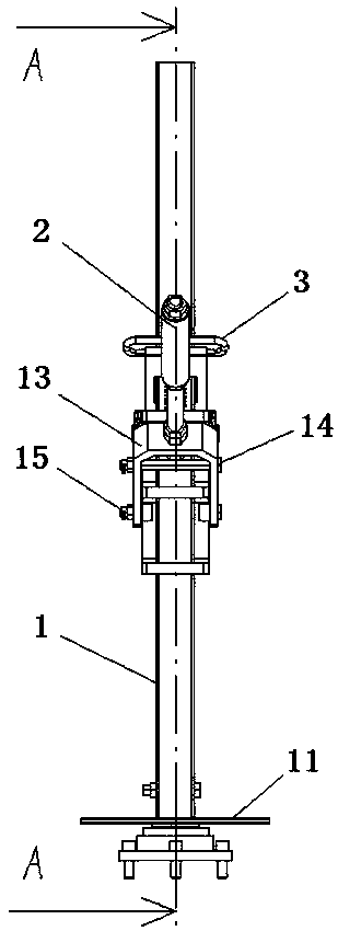
[0027] like Figure 1~5 As shown, the hoisting tooling of this embodiment includes a main pole 1, a lifting handle 2, a lowering handle 3 and a moving frame 4, wherein:

[0028] The main strut 1 has a rectangular cross-section, which is formed by socketing the upper hollow rod and the lower solid rod, and is fixedly connected by bolts 5 and nuts 6 at the junction of the hollow rod and the solid rod; the main strut 1 The surface is provided with anti-skid lines (not shown in the figure), the bottom of the main pole 1 is rotatably mounted on the bearing seat 8 through the bearing 7, and the bearing seat is fixed on the running trolley 10 by a number of uniformly distributed hexagon socket head bolts 9. The main pole 1 is fixedly provided with a fixed plate 11 above the bearing, and the fixed plate 11 is attached to...


PUM


Abstract

The invention provides a hoisting fixture which is convenient in operation, simple in structure, diversified in function and low in cost. The hoisting fixture comprises a main support rod, an ascending handle, a descending handle and a moving frame. The moving frame is formed by at least two horizontal plates and one vertical plate. The horizontal plates are upwards and downwards alternately arranged and the vertical plate is fixedly connected at the same side of the horizontal plates. The horizontal plates are provided with through holes. The main support rod passes through the through holesof the horizontal plates. The end part of the ascending handle is a U-shaped frame. Two arms of the U-shaped frame are connected through a limiting rod and a rotation shaft. The limiting rod and the rotation shaft are positioned at two sides of the main support rod. The rotation shaft passes through a shaft sleeve installed on the vertical plate. The ascending handle is connected with the moving frame through a first spring. The top end of the moving frame is provided with a limiting frame. An opening direction of the limiting frame faces to the main support rod. The end part of the descendinghandle is a frame-type structure. The main support rod passes through the frame-type structure. One end, away from the descending handle, of the frame-type structure is stretched into the limiting frame. The descending handle is connected with the moving frame through a second spring.

Description

technical field [0001] The invention belongs to the technical field of automobile design and manufacture, and in particular relates to a hoisting tool. Background technique [0002] In the whole vehicle manufacturing process, it is often necessary to hoist, transfer and store heavier sub-assemblies; some stations cannot use traditional hoists and other spreaders due to reasons such as location and production requirements, and using cantilever cranes or forklifts will greatly Increase the cost, and there are still many problems such as crossover of production operations, storage and transshipment; and purely manual hoisting is too heavy, inefficient, and has potential safety hazards. In this way, a suitable and flexible hoisting auxiliary structure is needed to assist manual hoisting. Reduce the labor intensity of operators and improve hoisting efficiency. Contents of the invention [0003] The purpose of the present invention is to provide a hoisting tool with convenient ...

Claims


Application Information

Patent Timeline
Patent Type & Authority Patents(China)
IPC IPC(8): B66D3/00
CPCB66D3/00
Inventor 贾岫岩陶立虎张凤娇
Owner CHERY AUTOMOBILE CO LTD
Learn More