Composite gas bearing with surface texture and surface texture design method

A surface texture, gas bearing technology, applied in the direction of rotating bearings, bearings, bearing components, etc., can solve problems such as insufficient bearing capacity

Active Publication Date: 2018-09-21
XIAN UNIV OF TECH
View PDF9 Cites 6 Cited by
  • Summary
  • Abstract
  • Description
  • Claims
  • Application Information

AI Technical Summary

Problems solved by technology

[0005] The purpose of the present invention is to provide a combined gas bearing with surface texture, which so

Method used


Image

  • Composite gas bearing with surface texture and surface texture design method
  • Composite gas bearing with surface texture and surface texture design method
  • Composite gas bearing with surface texture and surface texture design method

Examples


Embodiment 1

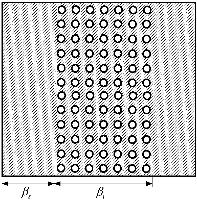
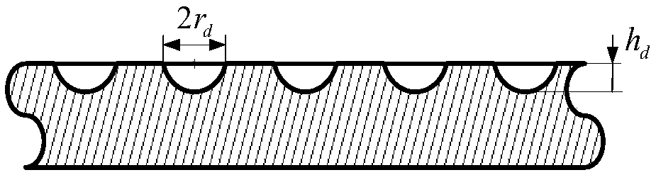
[0098] Such as figure 2 and image 3 As shown, the surface texture 3 is in the form of pits, and the shape of the pits is spherical. The axial surface texture rate of the spherical pit (the axial width of the surface texture area b t The ratio to the width b of the tilting pad 2) t is 100%; the circumferential surface texture rate (circumferential angle β of the surface textured area t The ratio of the wrapping angle β to the tilting pad block 2) s takes a value between 10% and 50%; the ratio of the surface texture initiation angle of the spherical pit (the angle β sThe ratio of the wrapping angle β to the tilting pad 2)k takes a value between 0% and 50%; the depth of the spherical pit h d Values ​​between 10 and 100 microns; radius r of spherical dimples d Take values ​​between 50 and 200 microns.

Embodiment 2

[0100] Such as Figure 4 and Figure 5 As shown, the surface texture 3 is in the form of pits, and the shape of the pits is cylindrical. Axial surface texture rate of cylindrical pits (axial width of surface textured area b t The ratio to the width b of the tilting pad 2) t is 100%; the circumferential surface texture rate (circumferential angle β of the surface textured area t The ratio of the wrapping angle β to the tilting pad block 2) s takes a value between 10% and 50%; the surface texture starting angle ratio of the cylindrical pit (the angle β between the surface texture and the starting edge of the tilting pad s The ratio of the wrapping angle β to the tilting pad 2)k is between 0% and 50%; the depth h of the cylindrical pit d Values ​​between 10 and 100 microns; radius r of the cylindrical pit d Take values ​​between 50 and 200 microns.

Embodiment 3

[0102] Such as Figure 6 and Figure 7 As shown, the surface texture 3 is in the form of pits, and the shape of the pits is square. The axial surface texture rate of the square pit (the axial width of the surface texture area b t The ratio to the width b of the tilting pad 2) t is 100%; the circumferential surface texture rate (circumferential angle β of the surface textured area t The ratio of the wrapping angle β to the tilting pad block 2) s takes a value between 10% and 50%; the ratio of the starting angle of the surface texture of the square pit (the angle β s The ratio of the wrapping angle β to the tiltable tile block 2)k takes a value between 0% and 50%; the depth h of the square pit d Values ​​between 10 and 100 microns; radius r of the square pit d Take values ​​between 50 and 200 microns.


PUM

PropertyMeasurementUnit
Depthaaaaaaaaaa
Radiusaaaaaaaaaa
Widthaaaaaaaaaa

Abstract

The invention discloses a composite gas bearing with surface texture. The composite gas bearing comprises a half-circular-arc-shaped fixed tile block, half-circular-arc-shaped inclinable tile block units are arranged at the position directly facing an opening of the fixed tile block, the fixed tile block and the inclinable tile block units enclose a cylinder together, the inner surfaces of the inclinable tile block units are provided with the surface texture, and the outer surfaces of the inclinable tile block units are provided with inclinable tile block supporting bodies. The invention further discloses a surface texture design method for the composite gas bearing with the surface texture, by means of adoption of genetic evolution strategies and dynamic application of operations of selection, crossover, mutation and the like, optimal allocation of inclinable tile block surface texture shapes, dimension parameters and distribution positions is realized, so that the bearing performanceof the composite gas bearing with the surface texture is furthest improved, and the service reliability of the bearing is improved.

Description

technical field [0001] The invention belongs to the technical field of dynamic lubricating devices for gas bearings, in particular to a combined gas bearing with surface texture, and also to a surface texture design method. Background technique [0002] Combined gas bearings with surface texture have been widely used in the field of new-generation miniature high-speed power drives such as micro gas turbine generator sets and new high-speed high-energy motors due to their characteristics of no pollution, low noise, low cost and high speed. However, with the development of a new generation of miniature high-speed power drives towards high efficiency and high service reliability, the service conditions of composite gas bearings with surface texture are becoming more and more severe. The performance requirements of gas bearings are also getting higher and higher. At present, the root of restricting the performance of combined gas bearings with surface texture is mainly the load...

Claims


Application Information

Patent Timeline
IPC IPC(8): F16C17/12F16C33/04G06N3/12G06F17/50
CPCF16C17/12F16C33/046G06N3/126G06F30/17
Inventor 张永芳吕延军刘成李莎康建雄
Owner XIAN UNIV OF TECH
Why Eureka
Try Eureka