Direct-current leakage current test device

A DC leakage and current testing technology, applied in the direction of measuring devices, measuring current/voltage, measuring electrical variables, etc., can solve the influence of the operator's boosting and reading measurement data, different DC leakage current values, and inconvenient pressure and reading and other problems, to achieve the effect of reducing life damage, improving test efficiency, efficient and reliable transmission and reading

Inactive Publication Date: 2018-09-21
JIANGSU ELECTRIC POWER CO
View PDF6 Cites 2 Cited by
  • Summary
  • Abstract
  • Description
  • Claims
  • Application Information

AI Technical Summary

Problems solved by technology

[0003] In the process of testing the DC leakage current of the insulation test product, a DC microammeter is required. The conventional DC microammeter is connected to the test circuit through the test wire. Affected by the leakage current to the ground, the position of the microampere meter is different. , the measured value of the DC leakage current is also different, which has a great influence on the measurement results
In order to ensure the accuracy of the test data, the microammeter is usually connected to the DC high voltage input terminal. Therefore, during the test boosting process, in order to ensure a certain safety distance, the operator needs to observe the reading of the DC microammeter from a long distance. It brings great inconvenience to test pressurization and reading
In addition, in the actual on-site observation, it is also affected by the light environment on site. If the site is backlit or the meter is reflective, the operator will be seriously affected when boosting voltage and reading measurement data.
These unfavorable factors may cause the test product to withstand long-term DC high voltage, resulting in potential damage to the life of the test product

Method used


Image

  • Direct-current leakage current test device
  • Direct-current leakage current test device
  • Direct-current leakage current test device

Examples


Embodiment 1

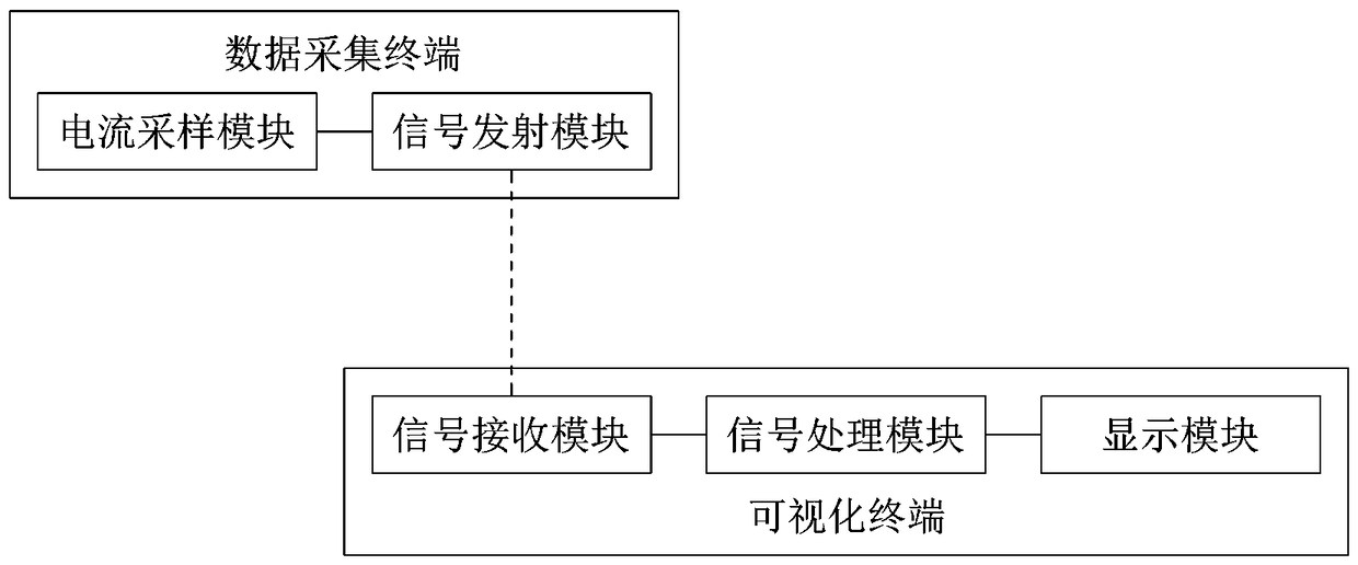
[0023] Embodiment one: as attached figure 1 As shown, a DC leakage current testing device for testing the DC leakage current of an insulation test object includes a data acquisition terminal and a visualization terminal that are separately set up and capable of remote communication.

[0024] The data acquisition terminal is connected with the insulation test object under test, and it is used for sampling the DC leakage current of the insulation test object and sending out a remote signal containing the information of the DC leakage current. The visualization terminal communicates remotely with the data acquisition terminal and is used to receive and analyze the remote signal to display the DC leakage current information.

[0025] The data acquisition terminal includes a current sampling module for sampling the DC leakage current of the insulation test object, and a signal transmitting module connected with the current sampling module and transmitting a remote signal. The visu...


PUM


Abstract

The invention relates to a direct-current leakage current test device. The direct-current leakage current test device comprises a data acquisition terminal and a visual terminal, wherein the data acquisition terminal is connected with an insulating test product, samples the direct-current leakage current and sends out a remote signal containing the direct-current leakage current information; the visual terminal communicates with the data acquisition terminal, receives and analyzes the remote signal and then displays the direct-current leakage current information. The data acquisition terminalcomprises a current sampling module and a signal emitting module for emitting the remote signal; the visual module comprises a signal receiving module for receiving the remote signal, a signal processing module and a display module. The signal emitting module is an infrared emitting module for emitting an infrared signal; the signal receiving module is an infrared receiving module for receiving the infrared signal. Test data can be transmitted and read efficiently and reliably under the condition that the safe distance of test pressurizing is reached; an operator can control the pressurizing time conveniently, the life damage caused by long-time pressurizing of the insulating test product is reduced, and the test efficiency is improved.

Description

technical field [0001] The invention belongs to the technical field of electric power detection, and in particular relates to a DC leakage current testing device for an insulation test product. Background technique [0002] The DC leakage current test of the insulation test product is a routine preventive test. For a good insulation test product, its volt-ampere characteristic should be similar to a straight line. When the insulation of the test product is defective (partial or complete) or there is moisture, the leakage conduction current increases sharply, so that the volt-ampere characteristic curve is not a straight line. Therefore, it is possible to judge whether the insulation is defective or damp by measuring the size of the leakage current. [0003] In the process of testing the DC leakage current of the insulation test product, a DC microammeter is required. The conventional DC microammeter is connected to the test circuit through the test wire. Affected by the lea...

Claims


Application Information

Patent Timeline
Patent Type & Authority Applications(China)
IPC IPC(8): G01R19/00G08C23/04
CPCG01R19/00G08C23/04
Inventor 王国栋张聪潘晓明单陆伟田志勇奚露露薛曦王悦心
Owner JIANGSU ELECTRIC POWER CO
Why Eureka
Try Eureka