
Interpupillary distance regulation device, head-wearing display device and step-by-step regulation mechanism

A technology of interpupillary distance adjustment and accommodating slot, which is applied in mechanical control devices, control/adjustment systems, devices to prevent/restrict/restore the movement of parts of the control mechanism, etc. , error-prone teeth and other problems, to achieve the effect of high transmission sensitivity, reducing the difficulty of operation, and enhancing the effect of centering

Active Publication Date: 2018-09-21
BOE TECH GRP CO LTD +1
View PDF4 Cites 6 Cited by
  • Summary
  • Abstract
  • Description
  • Claims
  • Application Information

AI Technical Summary

Problems solved by technology

The steel shaft of this type of design is thinner and the thread pitch is small, so that the operation of turning the steel shaft during adjustment is laborious, and the adjustment value cannot be obtained intuitively;
[0005] 2. Rack type, that is, a rack is added to the lens barrel, and the left and right lens barrels are meshed with a gear at the same time, and the interpupillary distance is directly adjusted by moving the lens barrel. Although this type of mechanism is simple and effective, it cannot be adjusted when wearing it. Distance adjustment operation is inconvenient to use;
[0006] 3. Pulley type, the lens barrel is driven by the synchronous belt and synchronous wheel mechanism. This kind of product has poor assembly performance, and there is no self-locking function after adjustment. It is easy to make wrong teeth and cannot directly obtain the value of interpupillary distance adjustment.

Method used


Image

  • Interpupillary distance regulation device, head-wearing display device and step-by-step regulation mechanism
  • Interpupillary distance regulation device, head-wearing display device and step-by-step regulation mechanism
  • Interpupillary distance regulation device, head-wearing display device and step-by-step regulation mechanism

Examples


Embodiment Construction

[0039] Embodiments of the present invention are described in detail below, examples of which are shown in the drawings, wherein the same or similar reference numerals designate the same or similar elements or elements having the same or similar functions throughout. The embodiments described below by referring to the figures are exemplary only for explaining the present invention and should not be construed as limiting the present invention.

[0040]The present invention provides an interpupillary distance adjustment device, which is suitable for a head-mounted display device (or a virtual display device), and is used for connecting with a lens barrel assembly to adjust the distance between two lens barrel assemblies, so as to avoid unsuitable interpupillary distance. Causes the image to be unclear and deformed, and is suitable for users with different pupil distances. Preferably, the interpupillary distance adjustment range of the interpupillary distance adjustment device of ...


PUM


Abstract

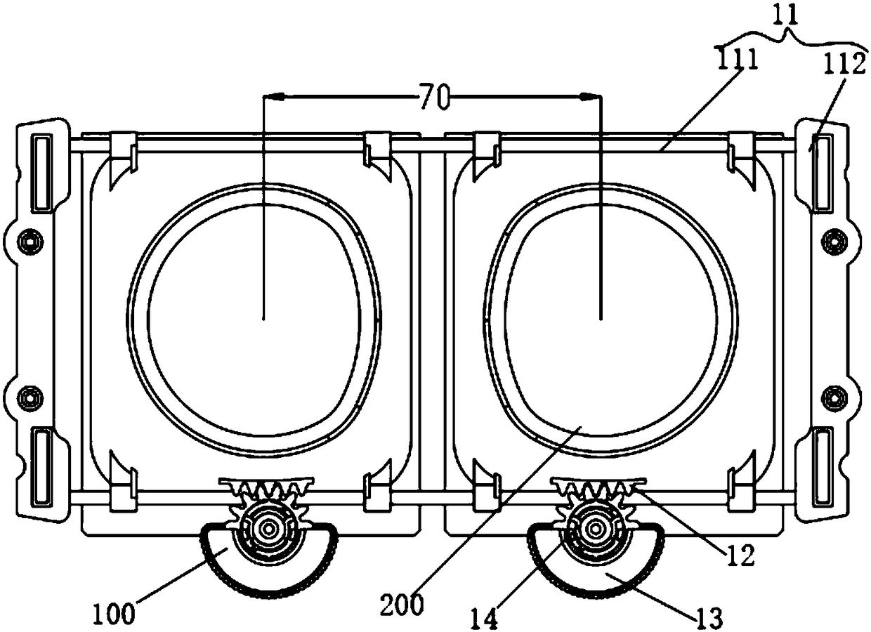
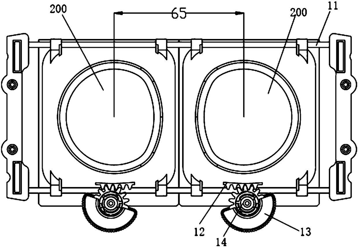
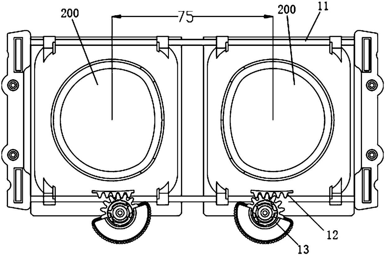
The present invention provides an interpupillary distance regulation device, a head-wearing display device and a step-by-step regulation mechanism. The interpupillary distance regulation device comprises: a guidance shaft configured to install two lens cone modules and allow the two lens cone modules to slide in an opposite direction in a mode of facing each other or being far away from each other; a pair of racks respectively arranged on the lens cone modules; a pair of dial gears, wherein the gear portions of the dial gears are in one-to-one corresponding engaging with the racks, and dial portions are configured to receive external action force to drive the gear portions to rotate; and a dial gear shaft configured to install the dial gears to be the housing of the head-wearing display device and allow the dial gears to rotate around the dial gear shaft. The interpupillary distance regulation device employs the two dial gears to correspondingly drive the two lens cone modules to slideon the guidance shaft so as to achieve increasing or decreasing of the distance between the two lens cone modules and achieve interpupillary distance regulation, and is simple in structure and convenient to use.

Description

technical field [0001] The present invention relates to the technical field of head-mounted display devices, and in particular to a pupil distance adjustment device, a head-mounted display device using the pupil distance adjustment device, and a step-by-step adjustment mechanism applicable to the pupil distance adjustment device. Background technique [0002] With the development of science and technology, the application of virtual display technology in people's production and life is becoming more and more extensive. In particular, the head-mounted display device is the most widely used. The head-mounted display device is a stereoscopic display that uses people's left and right eyes to obtain information differences and guides users to create a feeling of being in a virtual environment. Its display principle is that the left and right eye screens display the images of the left and right eyes respectively, and the human eye will generate a three-dimensional feeling in the b...

Claims


Application Information

Patent Timeline
IPC IPC(8): G02B27/01
CPCG02B27/0176G02B2027/0134G02B7/12G05G1/10G05G5/06G02B27/0172G02B2027/0123G02B2027/0138G02B2027/0141
Inventor 田文红张浩陈丽莉马占山孙志宇井颢然
Owner BOE TECH GRP CO LTD
Learn More