Built-in radial permanent magnet rotor structure

A permanent magnet rotor, permanent magnet technology, applied in the shape/style/structure of the magnetic circuit, the rotating parts of the magnetic circuit, the magnetic circuit, etc. It can reduce the magnetic flux leakage coefficient, simplify the structure and improve the starting performance.

Pending Publication Date: 2018-09-21
XIANGYANG HANGLI ELECTROMECHANICAL TECH DEV
View PDF0 Cites 1 Cited by
  • Summary
  • Abstract
  • Description
  • Claims
  • Application Information

AI Technical Summary

Problems solved by technology

Especially when the number of poles of the motor is large, the magnetic isolation bridge will occupy a large size space, the mechanical strength of the rotor core is poor, and the installation size of the radial permanent magnet is also reduced, resulting in the permanent magnet not being able to provide enough per pole. Magnetic flux, which eventually leads to increased motor size, increased cost, and reduced power density

Method used


Image

  • Built-in radial permanent magnet rotor structure
  • Built-in radial permanent magnet rotor structure
  • Built-in radial permanent magnet rotor structure

Examples


Embodiment Construction

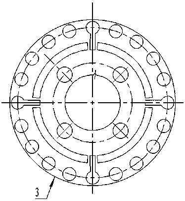
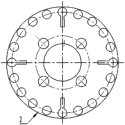
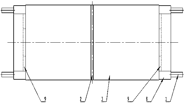
[0023] figure 1 Among them, there are four built-in radial permanent magnet slots on the rotor punching plate 3, and 16 circular cage holes and 4 special-shaped cage holes are evenly distributed on the outer circle. The top of the 4 special-shaped cage holes is circular, The bottom is a rectangle, connected up and down. This structure integrates 4 rectangular magnetic isolation bridges and circular cage bars, which can provide a larger permanent magnet space and improve the power density of the motor. At the same time, the cage bars and the magnetic isolation bars are cast at the same time when casting aluminum. It reduces the process flow and enhances the mechanical strength of the rotor core. Four circular holes are uniformly distributed in the middle of the punching sheet, and are used for fixing the rotor punching sheet 3 and the rotor spacer 2 together through the fixing rod 4, thereby enhancing the mechanical strength of the rotor core 10. The rotor punch 3 is made of...


PUM


Abstract

The invention provides a built-in radial permanent magnet rotor structure, which comprises a rotation shaft, and a rotor core sleeved on the rotation shaft. The rotor core is an integrated body formedby connecting at least two iron core sections through cage bars and end rings. Each iron core section comprises a hollow rotor section and at least two permanent magnets in opposite poles, wherein the permanent magnets are arranged on the hollow rotor section. The magnetic poles of the permanent magnets of the adjacent two iron core sections are same. The hollow rotor section is formed by superposing a plurality of rotor punching sheets. The cage bars comprise a plurality of cage bars 1 and more than two cage bars 2. The cross section of the cage bar 1 is circular; the cross section of the cage bar 2 comprises a circular portion and a rectangular portion connected with the circular portion. The cage bars 1 are arranged between the circular portions of the adjacent two cage bars 2. The permanent magnets are arranged between the rectangular portions of the adjacent two cage bars 2. The rectangular portion of the cage bar 2 is a magnetic isolation bar, which carries out magnetic isolation on the left and right two permanent magnets, and replaces conventional air gap magnetic isolation, thereby achieving a purpose of carrying out magnetic isolation on the adjacent permanent magnets. The built-in radial permanent magnet rotor structure has the advantages of compact structure, large power density, reliable performance and long service life.

Description

technical field [0001] The invention relates to a permanent magnet rotor structure. Background technique [0002] Permanent magnet synchronous motors can be divided into motors without starting windings and motors with starting windings according to whether there is a starting winding on the rotor. The former is often called a speed-regulating permanent magnet synchronous motor, and the latter is often called an asynchronous starting permanent magnet synchronous motor. The asynchronous starter permanent magnet motor can be used for speed regulation operation and start with the asynchronous torque generated by the starter winding at a certain frequency and voltage. When used in a transmission system with adjustable frequency and a large starting torque, it will form a A variable speed permanent magnet synchronous motor with a damper (starter) winding. [0003] According to the position of the permanent magnet in the rotor, the rotor magnetic circuit structure of the permanen...

Claims


Application Information

Patent Timeline
Patent Type & Authority Applications(China)
IPC IPC(8): H02K1/27H02K1/28H02K21/46
CPCH02K1/2706H02K1/28H02K21/46
Inventor 张绍睿钱波杜小锋石艳范超
Owner XIANGYANG HANGLI ELECTROMECHANICAL TECH DEV
Why Eureka
Try Eureka