Supercharge Your Innovation With Domain-Expert AI Agents!

Coil unit, wireless power transmitting device, wireless power receiving device, and wireless power transmission system

A coil unit and coil technology, applied in transmission systems, near-field transmission systems, circuit devices, etc., can solve problems such as the reduction of power transmission efficiency, and achieve the effect of suppressing the reduction of magnetic coupling and the change of inductance.

Active Publication Date: 2018-09-25
TDK CORP
View PDF10 Cites 4 Cited by
  • Summary
  • Abstract
  • Description
  • Claims
  • Application Information

AI Technical Summary

Problems solved by technology

That is, the above-mentioned problem is that when the first coil with a relatively large winding area and the second coil with a relatively small winding area are arranged and used to face each other, if the positional relationship of these planes deviates, the The inductance varies greatly, and the result can be summarized as a change in the resonance state of the resonance circuit composed of the first coil and the second coil, and the power transmission efficiency decreases.

Method used


Image

  • Coil unit, wireless power transmitting device, wireless power receiving device, and wireless power transmission system
  • Coil unit, wireless power transmitting device, wireless power receiving device, and wireless power transmission system
  • Coil unit, wireless power transmitting device, wireless power receiving device, and wireless power transmission system

Examples


Embodiment Construction

[0055] Hereinafter, embodiments of the present invention will be described in detail with reference to the drawings.

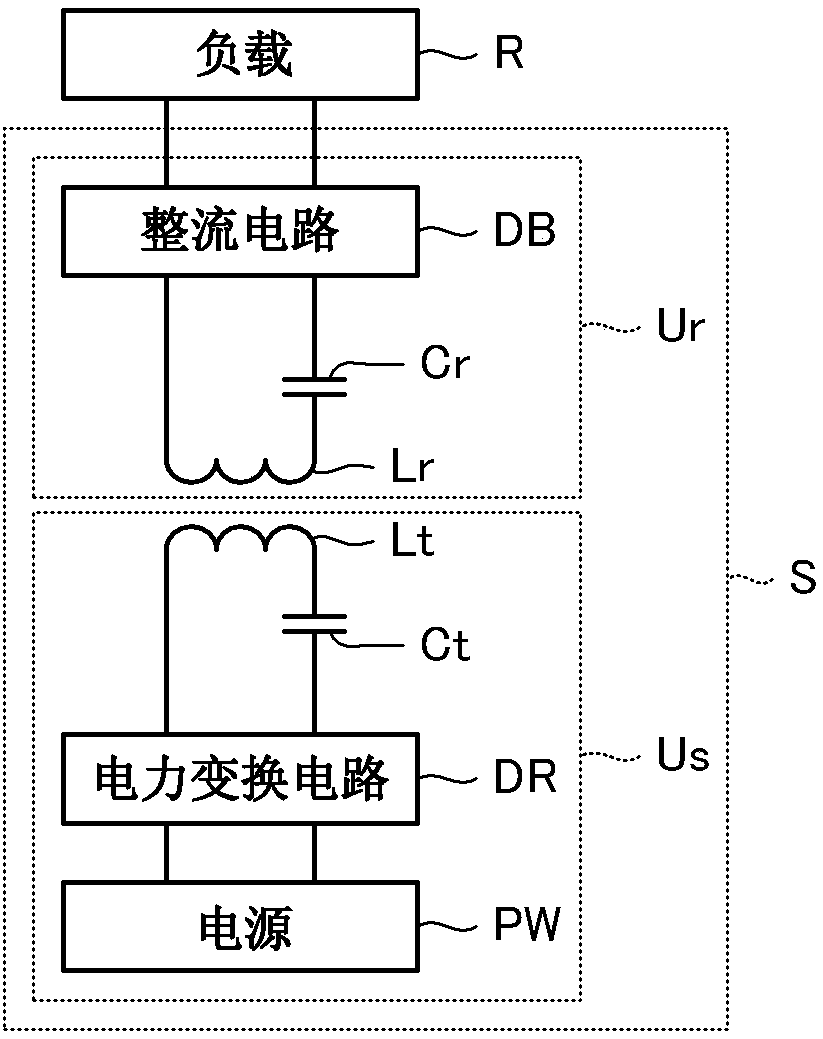
[0056] figure 1 It is a figure which shows the structure of the wireless power transmission system S which concerns on embodiment of this invention. The wireless power transmission system S is a device for wirelessly transmitting electric power, and as shown in the figure, includes a wireless power supply device Us for wirelessly transmitting electric power, and a wireless power receiving device Ur for wirelessly receiving electric power.

[0057] The wireless power transmission system S is used to supply power to mobile devices such as smartphones and vehicles such as electric cars. When a mobile device such as a smartphone is used as a power supply target, the wireless power supply device Us is a charging pad installed on a table, for example, and the wireless power receiving device Ur is a built-in device of the mobile device. When a vehicle such as an e...


PUM


Abstract

The present invention provides a coil unit capable of suppressing a change in the inductance factors of the power feeding coil (10) even when a positional relationship between the power feeding coil (10) and the power receiving coil (20) is deviated. A coil unit (Lr) is provided with a power receiving coil (20) wound in a plane spiral shape so as to have an opening portion (20a) at a center with asmaller winding area than the power feeding coil (10); a magnetic member (21) disposed along the surface of the power receiving coil (20) on the opposite side as seen from the power supply coil (10);the magnetic member 21 is composed of a plurality of magnetic bodies (21a to 21d) that are disposed apart from each other. The magnetic bodies (21a to 21d) are arranged such that the winding portionof the power receiving coil (20) and the opening portion (20a) overlap each other in plan view. The width s1 which is a separation distance between two adjacent magnetic bodies among the magnetic bodies (21a to 21d) is 3% or more and 30% or less of the maximum width d1 of the power receiving coil (20).

Description

technical field [0001] The invention relates to a coil unit, a wireless power supply device, a wireless power receiving device, and a wireless power transmission system. Background technique [0002] In recent years, attention has been drawn to wireless power transmission technologies for charging mobile devices such as mobile devices and electric vehicles by using electromagnetic induction between opposing primary (power supply) coils and secondary (power receiving) coils. In response to this technology, research has been conducted on a technology that can transmit power with high efficiency and low loss by connecting capacitors in series or parallel to coils to form a resonant circuit. [0003] In Patent Document 1, a non-contact power transmission device that performs power transmission using the wireless power transmission technique described above is disclosed. This non-contact power transmission device is composed of a primary coil provided on a power supply side memb...

Claims


Application Information

Patent Timeline
Patent Type & Authority Applications(China)
IPC IPC(8): H02J7/02H02J50/12H02J50/90H02J5/00H01F38/14H01F27/28H01F27/245
CPCH02J5/005H02J7/025H02J50/90H02J50/12H01F27/245H01F27/2823H01F27/2871H01F38/14H01F27/363H02J50/70H02J50/005H01F27/36H04B5/24H04B5/79
Inventor 千代宪隆
Owner TDK CORP
Features
  • R&D
  • Intellectual Property
  • Life Sciences
  • Materials
  • Tech Scout
  • Unparalleled Data Quality
  • Higher Quality Content
  • 60% Fewer Hallucinations
Learn More