A high-efficiency time-domain broadband beamforming circuit and method

A broadband and beam technology, applied in the field of high-efficiency time-domain broadband beamforming circuits, can solve problems such as joint optimization of channel equalization technology, inability to quickly and flexibly adjust beam pointing, complex structure, etc., to achieve real-time broadband digital beamforming , Solve the distortion of the broadband beam pattern and reduce resource consumption

Active Publication Date: 2022-04-01
NANJING UNIV OF SCI & TECH
View PDF21 Cites 0 Cited by
  • Summary
  • Abstract
  • Description
  • Claims
  • Application Information

AI Technical Summary

Problems solved by technology

[0005] Existing broadband digital beamforming circuits and methods based on time-domain delay are generally aimed at broadband beamforming applications with fixed beam pointing, and cannot quickly and flexibly adjust beam pointing, and do not consider the actual problem of joint optimization with channel equalization technology. complex

Method used


Image

  • A high-efficiency time-domain broadband beamforming circuit and method
  • A high-efficiency time-domain broadband beamforming circuit and method
  • A high-efficiency time-domain broadband beamforming circuit and method

Examples


Embodiment 1

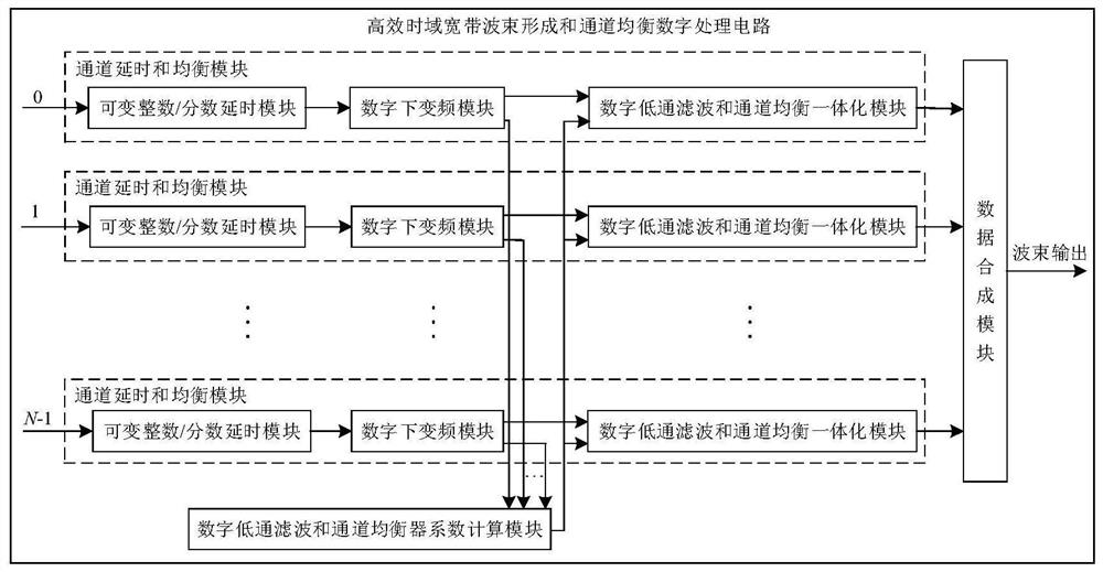
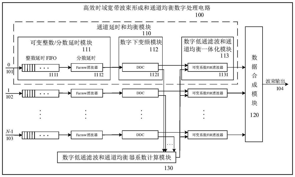
[0057] Aiming at the problems of inaccurate beam pointing and channel mismatch caused by the aperture effect, the present invention provides a high-efficiency time-domain broadband beamforming digital processing circuit using a cascaded FIR transverse filter structure, and realizes broadband beams with accurate beam pointing Formed and compensated for channel-to-channel mismatch. figure 1 A general block diagram of the digital processing circuit is given, figure 2 A detailed block diagram of each module is given. All logic functions of the circuit can be implemented in a single FPGA, mainly realizing digital time domain delay, digital down-conversion, filter extraction, channel equalization and beamforming and other functions. The circuit is composed of N channel delay and equalization modules 110 , a data synthesis module 120 and a digital low-pass filter and channel equalizer coefficient calculation module 130 . Wherein, each channel delay and equalization module 110 is co...

Embodiment 2

[0072] Sampling frequency f s = 200MHz, the echo signal is a broadband sweep signal, and its center frequency f 0 =50MHz, bandwidth B=30MHz. The circuit of the invention is used to complete broadband beam forming and channel equalization, and its working method includes initialization mode, channel equalization mode and normal working mode.

[0073] The steps to initialize the schema are:

[0074] Step 1. Calculate the coefficients of the Farrow filter according to the set delay accuracy and delay error within the bandwidth (obtainable from the document Weighted-least-squares design of variable fractional-delay FIRfilters using coefficient symmetry), and then insert Fixed coefficients for the variable fractional delay Farrow filter 1112 of the variable integer / fractional delay module 111;

[0075] According to the signal center frequency and sampling frequency, within the range of digital angular frequency ω∈[0.35π,0.65π], the ideal amplitude-frequency response of Farrow fi...


PUM


Abstract

The invention discloses a high-efficiency time-domain broadband beamforming circuit adopting a cascaded FIR transverse filter structure, which consists of N channel delay and equalization modules, a data synthesis module, and a digital low-pass filter and channel equalizer coefficient calculation Module composition. Among them, each channel delay and equalization module is composed of variable integer / fraction delay module, digital down-conversion module, digital low-pass filter and channel equalization integrated module. The present invention jointly optimizes the coefficients of the digital down-conversion low-pass filter and the channel equalization filter, and only uses one variable coefficient FIR filter to realize both functions, effectively reducing resource consumption. The present invention adopts the cascaded FIR transverse filter structure, through the joint optimization technology of delay function front and FIR filter, effectively reduces resource consumption, efficiently realizes time-domain broadband beamforming and channel equalization functions, and can be widely used in radar broadband Systems such as digital beamforming, microphone arrays, and sonar arrays.

Description

technical field [0001] The invention belongs to the field of broadband array signal processing, in particular to a high-efficiency time-domain broadband beam forming circuit and method using a cascaded FIR transverse filtering structure. Background technique [0002] Digital beamforming refers to the use of multiple sensors placed in different positions in space to form a sensor array to collect signals, and then form a desired pattern in the digital domain through a digital beamforming algorithm to improve the quality of useful signals in the airspace and suppress interference signals. [0003] The basic principle of digital beamforming is to control the delay of signals in the array to offset the spatial delay of signals from different directions, so that the signals between each array element can be added in phase to obtain beam pointing and directional gain. Because most of the traditional digital array systems are narrow-band systems with relatively small changes in the...

Claims


Application Information

Patent Timeline
Patent Type & Authority Patents(China)
IPC IPC(8): H03D7/14H03H17/00
CPCH03D7/14H03H17/00H03H2017/0081
Inventor 马晓峰张书瑞盛卫星郭明韩玉兵张仁李崔杰
Owner NANJING UNIV OF SCI & TECH
Why Eureka
Try Eureka