

Filter system of fish pond
A filtration system and fish pond technology, applied in fish farming, application, animal husbandry, etc., can solve the problems of insufficient water quality filtration treatment in fish ponds, affecting water flow speed and filtration effect, and poor device performance. Stability, improve the filtering effect, the effect of stable transmission ratio
- Summary
- Abstract
- Description
- Claims
- Application Information
AI Technical Summary
Problems solved by technology
Method used
Image

Examples
Embodiment 1
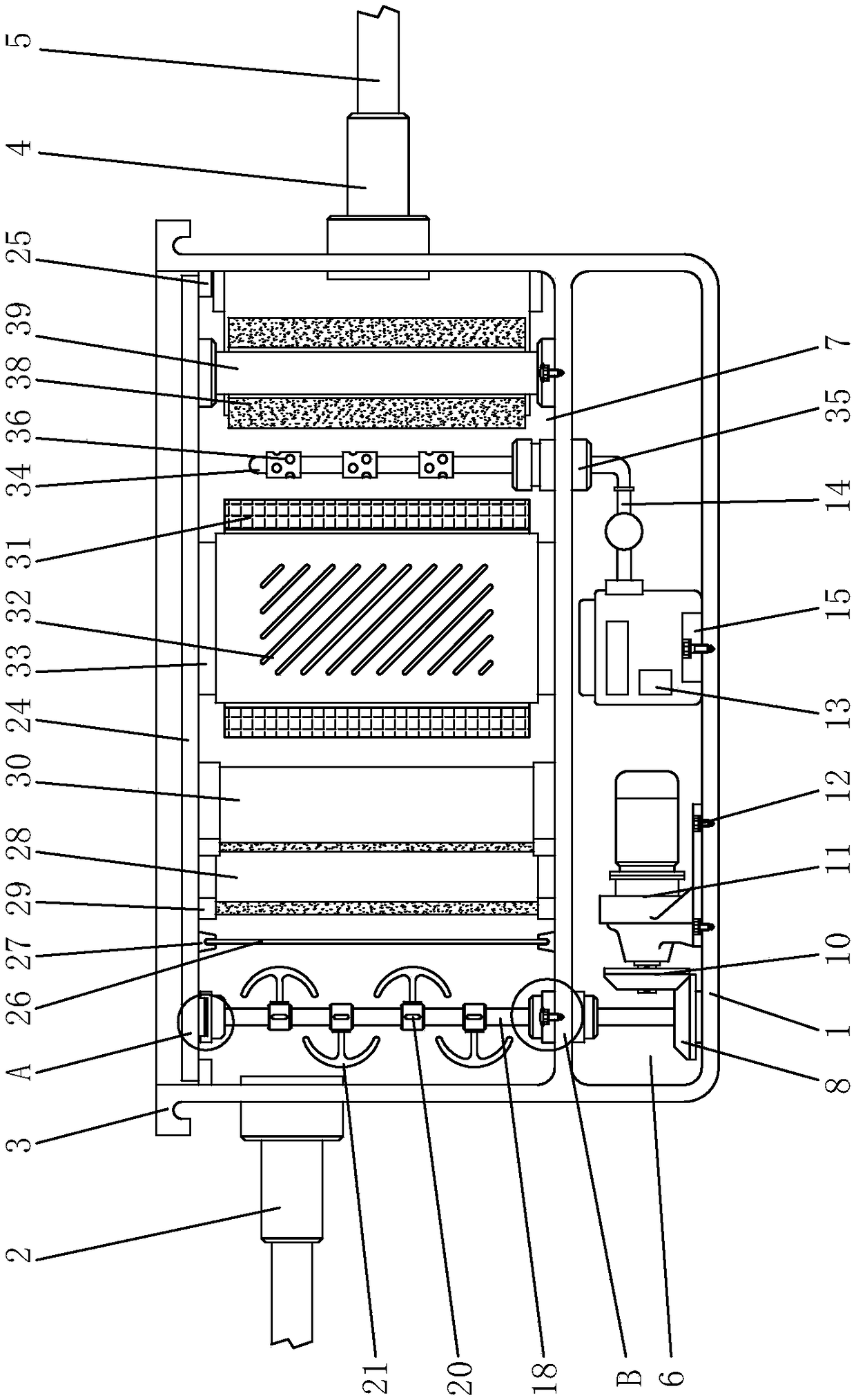
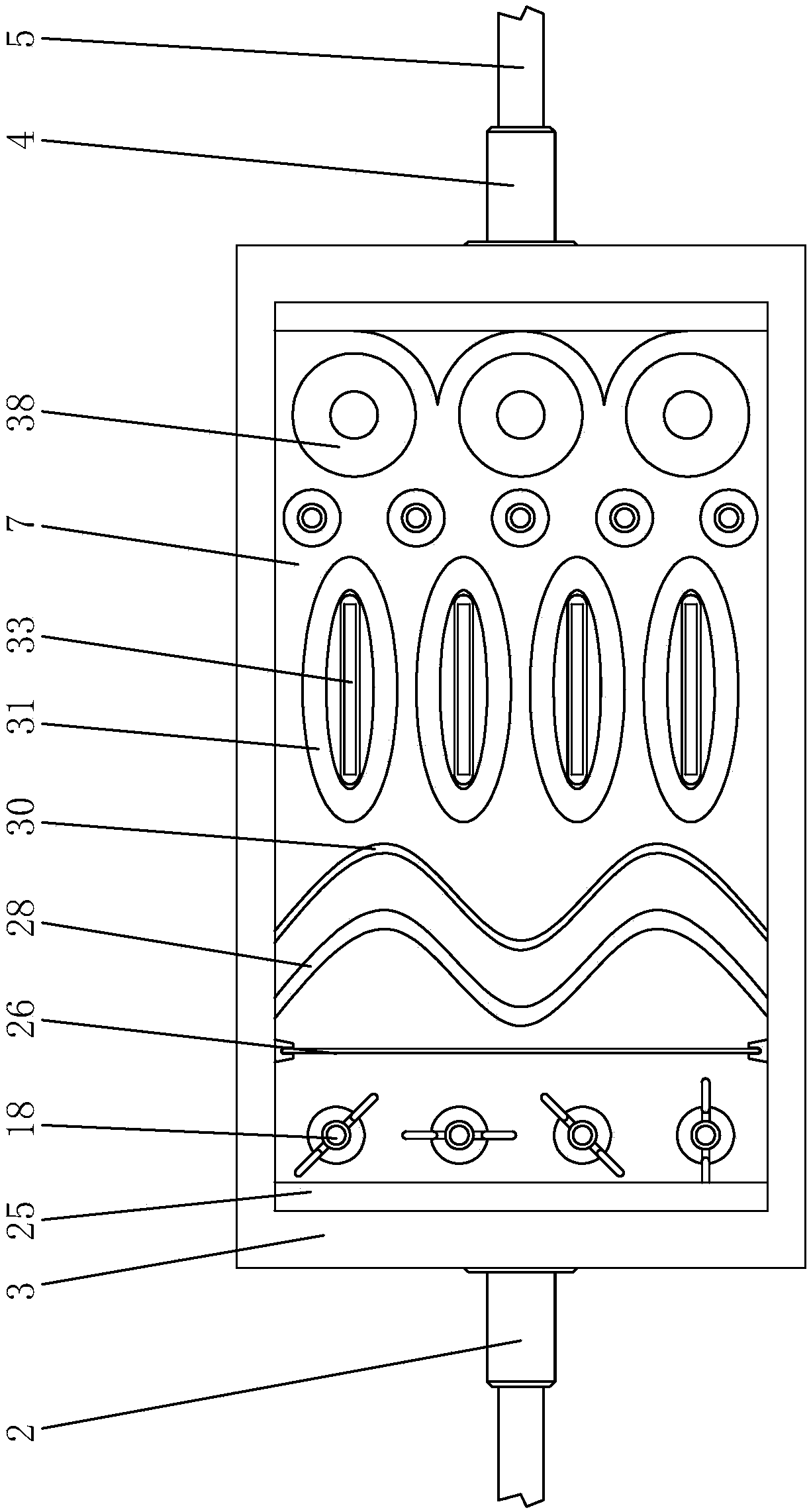
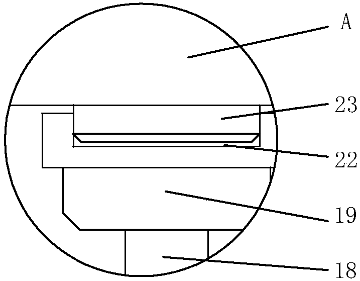
[0047] see Figure 1-5 , the present invention provides a technical solution: a filter system for fish ponds, including a box shell 1, a driving gear 10 and a filter screen 26, the upper left side of the box shell 1 is connected with a water inlet 2, and the water inlet 2 The top is provided with an eversion handle 3, and the water inlet 2 and the water outlet 5 are connected to the left and right ends of the box shell 1 through the conversion joint 4, and the level of the water inlet 2 is higher than the level of the water outlet 5, through the conversion The joint 4 can better introduce the water in the fish pond into the filter chamber 7, and can control the water flow velocity while introducing it, so as to avoid reducing the filtration quality because the water flow is too large. The right side of the box shell 1 A conversion joint 4 is installed on the side, and the right end of the conversion joint 4 is provided with a water outlet 5, and a power chamber 6 is provided u...
Embodiment 2
[0050] see Figure 6-11 , this embodiment also includes the following features on the basis of embodiment 1: the water inlet is connected with a filter pump for pumping water and performing preliminary filtration.
[0051] The filter pump includes a motor 91 , a pump casing 92 and a water wheel 96 rotatably installed in the pump casing and driven by the motor.
[0052] A pump cover 911 is connected to the lower end of the motor, and the pump cover is sealingly connected to the upper end of the pump casing with an open upper end, and a pump chamber is formed between the pump casing and the pump cover.
[0053] The middle of the lower end of the pump housing is integrally connected with a circular pipe-shaped water inlet pipe portion 921 , and the side wall of the pump housing is integrally connected with a water outlet joint 923 .
[0054] In the middle of the lower end of the motor is a polygonal drive shaft 912 coaxially connected to the motor rotor. The lower end of the dri...
PUM
 Abstract
Description
Claims
Application Information