
Oil smoke separation device

A technology of oil fume separation and separation disc, which is applied in the direction of oil fume removal, separation method, and dispersed particle separation, etc., can solve the problems affecting the effect of oil fume separation, affecting the service life of oil fume separation device, etc., and achieves good effects.

Pending Publication Date: 2018-09-28
广州特伊雅智能科技有限公司
View PDF5 Cites 0 Cited by
  • Summary
  • Abstract
  • Description
  • Claims
  • Application Information

AI Technical Summary

Problems solved by technology

However, due to the gap between the separation plate and the partition, the oil fume separation device has been used for a long time, and some oil fume will remain through the gap between the separation plate and the partition without being intercepted and separated. , not only affects the effect of subsequent oil fume separation, but also affects the service life of the oil fume separation device

Method used


Image

  • Oil smoke separation device
  • Oil smoke separation device
  • Oil smoke separation device

Examples


Embodiment

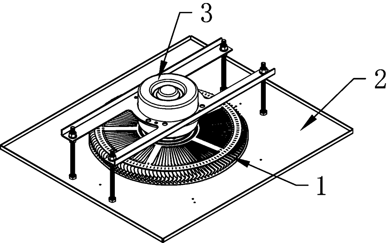
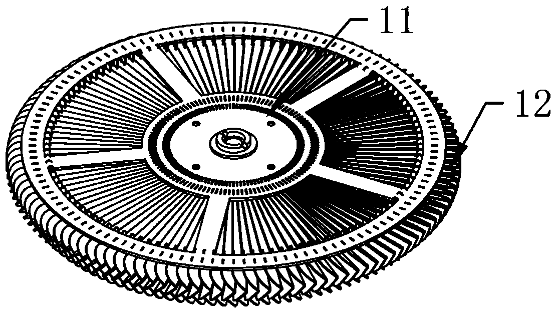
[0029] like figure 1 with figure 2 As shown, an oil fume separation device includes a separation disc 1, a separator 2 and a motor 3, the motor 3 is installed on the separation disc 1, and the upper layer of the separation disc 1 extends circumferentially larger than the lower layer along the circumferential direction. The extended size forms a shape with a wide top and a narrow bottom; the partition 2 is provided with a hollow structure, and the separation disc 1 is embedded in the hollow structure of the partition 2, and the lower layer of the separation disc 1 is in the same position as the partition 2 Flat, the upper edge of the separation disc 1 protrudes from the edge of the hollow structure of the separator 2.

[0030] By setting the separation disk 1 into a structure with a wide top and a narrow bottom, and the partition plate 2 is just flat with the narrow side part of the separation disk 1, so that the edge of the hollow structure of the partition plate 2 protrudes...


PUM

PropertyMeasurementUnit
diameteraaaaaaaaaa
heightaaaaaaaaaa

Abstract

The invention discloses an oil smoke separation device. The oil smoke separation device comprises a separation disc, a partition plate and a motor, wherein the motor is arranged on the separation disc;the size of the upper layer extending along the circumference of the separation disc is larger than that of the lower layer extending along the circumference, forming the shape of the upper width andthe lower narrowness; the partition plate is provided with a hollow structure, the separation disc is embedded on the hollow structure of the partition plate, and the lower layer position of the separation disc is flat with the partition plate, and the upper edge of the separation disc is projected on the edge of the hollow structure of the partition plate. Compared with the prior art, the oil smoke separation device can effectively separate the oil fume and effectively intercept the non-separated oil smoke.

Description

technical field [0001] The invention relates to the field of oil fume purification, and more particularly, to an oil fume separation device. Background technique [0002] At present, oil fume purification equipment has become one of the indispensable kitchen equipment in ordinary homes, production workshops, canteens and other places. Centrifugal fans have been widely used in oil fume purification equipment due to their advantages of large suction, low noise, and compact structure. Among them, due to the large production volume and frequent application, the oil fume purification equipment used in industry is much larger than the oil fume purification equipment used in ordinary households and canteens. The oil fume purification equipment used in ordinary households and canteens is far from meeting the needs of industrial production. , so it is necessary to use industrial-specific oil fume purification equipment. [0003] The oil fume purification equipment in the prior art ...

Claims


Application Information

Patent Timeline
Patent Type & Authority Applications(China)
IPC IPC(8): B01D45/04F24C15/20
CPCB01D45/04F24C15/20
Inventor 石明益
Owner 广州特伊雅智能科技有限公司
Learn More