Eureka AIR delivers breakthrough ideas for toughest innovation challenges, trusted by R&D personnel around the world.

Die-casting die cooling device

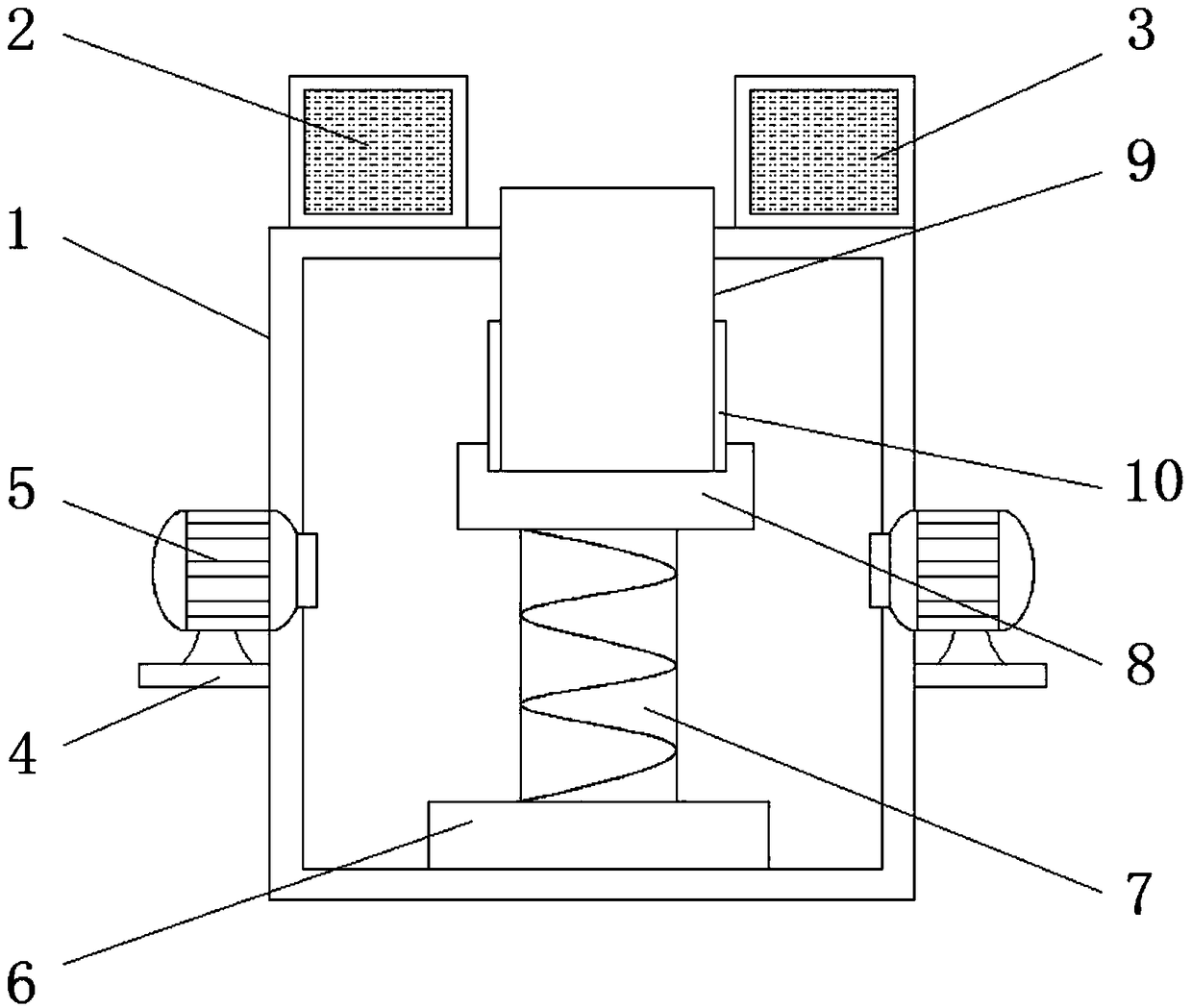
A cooling device and die-casting mold technology, applied in the field of mold cooling, can solve the problems of increased control, increased cycle, waste of paint, etc., to achieve the effects of ensuring quality, improving stability, and uniform cooling

Inactive Publication Date: 2018-09-28
芜湖新尚捷智能信息科技有限公司
View PDF11 Cites 4 Cited by
  • Summary
  • Abstract
  • Description
  • Claims
  • Application Information

AI Technical Summary

Problems solved by technology

[0002] The mold needs to be cooled after pouring in order to obtain a formed casting. The molten metal is injected into the mold cavity, releasing a large amount of heat in a very short time, which promotes the temperature of the mold to increase. Cooling measures are required to cool the mold. Therefore , in the processing and production of molds, the use of cooling devices is more common. There are certain disadvantages in the use of existing mold cooling devices. The cooling capacity of the mold is insufficient. The control of the process increases the unstable factors, increases the operation cycle, and wastes paint unnecessarily. At the same time, the cooling temperature required for castings with different wall thicknesses is different, and the cooling device cannot be adjusted conveniently, which reduces the cooling effect of the mold.

Method used


Image

  • Die-casting die cooling device
  • Die-casting die cooling device

Examples


Embodiment Construction

[0018] The following will clearly and completely describe the technical solutions in the embodiments of the present invention with reference to the accompanying drawings in the embodiments of the present invention. Obviously, the described embodiments are only some, not all, embodiments of the present invention.

[0019] In describing the present invention, it should be understood that the terms "upper", "lower", "front", "rear", "left", "right", "top", "bottom", "inner", " The orientation or positional relationship indicated by "outside", etc. is based on the orientation or positional relationship shown in the drawings, and is only for the convenience of describing the present invention and simplifying the description, rather than indicating or implying that the referred device or element must have a specific orientation, so as to Specific orientation configurations and operations, therefore, are not to be construed as limitations on the invention.

[0020] refer to Figure ...


PUM


Abstract

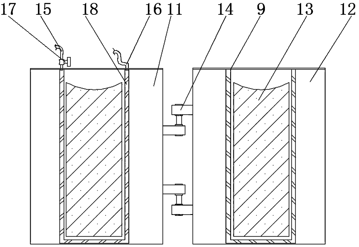
The invention discloses a die-casting die cooling device. The die-casting die cooling device comprises a cooling device shell; a return water tank is disposed on one side of the upper end of the cooling device shell; connecting plates are fixedly mounted at the two ends of the cooling device shell correspondingly; a lifting base is fixedly mounted on the lower portion of the interior of the cooling device shell; a lifting rod is disposed at the upper end of the lifting base; a die placement disc is fixedly mounted at the upper end of the lifting rod; a die-casting die is movably mounted on theupper surface of the die placement disc; fixing clamping plates are disposed on the sides, close to the die-casting die, of the two sides of the upper end of the die placement disc correspondingly; afirst die is disposed on one side of the interior of the die-casting die; a second die is disposed on the other side of the interior of the die-casting die; and connecting pins are disposed at the end, close to the second die, of the first die. The die-casting die cooling device is simple in structure, the die cooling uniformity can be improved, the dies can be fixed, and cooling treatment on die-casting dies which are different in wall thickness is convenient.

Description

technical field [0001] The invention relates to the technical field of mold cooling, in particular to a die-casting mold cooling device. Background technique [0002] The mold needs to be cooled after pouring in order to obtain a formed casting. The molten metal is injected into the mold cavity, releasing a large amount of heat in a very short time, which promotes the temperature of the mold to increase. Cooling measures are required to cool the mold. Therefore , in the processing and production of molds, the use of cooling devices is more common. There are certain disadvantages in the use of existing mold cooling devices. The cooling capacity of the mold is insufficient. The control of the process increases the unstable factors, increases the operation cycle, and wastes paint unnecessarily. At the same time, the cooling temperature required for castings with different wall thicknesses is different, and the cooling device cannot be adjusted conveniently, which reduces the co...

Claims


Application Information

Patent Timeline
IPC IPC(8): B22D17/22B22D17/32
CPCB22D17/2218B22D17/32
Inventor 程恭正
Owner 芜湖新尚捷智能信息科技有限公司
Why Eureka
Eureka Blog
Learn More