
An ultrasonic welding seat structure

An ultrasonic welding and ultrasonic technology is applied in the field of ultrasonic welding seat structure to achieve the effect of simple structure, convenient use and precise displacement adjustment

Active Publication Date: 2020-11-17
苏州昕源辰机械设备有限公司
View PDF8 Cites 0 Cited by
  • Summary
  • Abstract
  • Description
  • Claims
  • Application Information

AI Technical Summary

Problems solved by technology

[0003] The purpose of the present invention is to provide an ultrasonic welding seat structure to solve the problem of intelligent preparation and use of ultrasonic welding seats

Method used


Image

  • An ultrasonic welding seat structure

Examples


Embodiment 1

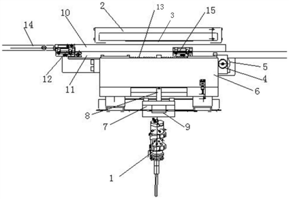
[0010] Example 1, such as figure 1 As shown, an ultrasonic welding seat structure is characterized in that: the ultrasonic welding seat structure includes an upper positioning adjustment structure and a lower connection structure connected to the ultrasonic welding head structure, and the ultrasonic welding head structure 1 is arranged on the lower connection structure. The lower part, the lower connection structure is arranged on the lower part of the upper positioning adjustment structure, and the upper positioning adjustment structure includes an upper connection block 2, an upper mobile platform 3 arranged at the lower part of the upper connection block, and a sliding platform arranged at the lower part of the upper mobile platform. The sliding adjustment structure and the inner connecting plate 5 arranged at the rear of the sliding adjusting structure, the lower connecting structure includes the lower connecting platform 6 arranged on the outer side between the sliding adj...


PUM


Abstract

The invention discloses an ultrasonic welding base structure. The ultrasonic welding base structure is characterized by comprising an upper positioning adjustment structure and a lower connecting structure for connecting with an ultrasonic welding head structure; the ultrasonic welding head structure is arranged at the lower part of the lower connecting structure; the lower connecting structure isarranged at the upper part of the upper positioning adjustment structure; the upper positioning adjustment structure comprises an upper connecting block, an upper movable platform arranged at the lower part of the upper connecting block, a slide adjusting structure arranged at the lower part of the upper movable platform, and an inner connecting plate arranged at the back part of the slide adjusting structure; and the lower connecting structure comprises a lower connecting table arranged on the outer side between the slide adjusting structure and the inner connecting plate, and a welding mechanism connecting module arranged at the lower part of the lower connecting table. The ultrasonic welding base structure has the beneficial effects of simple structure, convenience to use, guarantee ofmated use of intelligent robot equipment, guarantee of the precision of positioned welding and the convenience and the effectiveness of adjustment and displacement, and further improvement of the product quality.

Description

technical field [0001] The invention relates to an auxiliary part for ultrasonic welding, in particular to an ultrasonic welding seat structure. Background technique [0002] At present, in order to improve production efficiency and reduce production costs, many enterprises will apply automated processing equipment to the application of robots in actual production and processing. In the past, the ultrasonic welding seat was connected by a fixed seat, so the problem of inaccurate positioning often occurred during use, which affected the welding quality. And the structure part of the fixed seat in the past is suitable for the preparation and use of intelligent equipment. Contents of the invention [0003] The object of the present invention is to provide an ultrasonic welding seat structure to solve the problem of intelligent preparation and use of the ultrasonic welding seat. [0004] The technical solution adopted by the present invention to solve the technical problem i...

Claims


Application Information

Patent Timeline
Patent Type & Authority Patents(China)
IPC IPC(8): B23K20/10
CPCB23K20/10
Inventor 刘超
Owner 苏州昕源辰机械设备有限公司
Learn More