
Pressure maintaining jig for electronic device screen

A technology for electronic devices and screens, applied in workpiece clamping devices, manufacturing tools, material gluing, etc., can solve the problems of insufficient pressure holding jig, loose or warped screen, short wear life, etc., to prevent loosening. or warping, improving the pressure holding effect and prolonging the service life

Active Publication Date: 2018-09-28
GUANGDONG OPPO MOBILE TELECOMM CORP LTD
View PDF8 Cites 5 Cited by
  • Summary
  • Abstract
  • Description
  • Claims
  • Application Information

AI Technical Summary

Problems solved by technology

[0002] In the related art, the pressure holding fixture used for the screen of an electronic device is mainly a two-plate structure. The upper and lower covers of the two-plate structure are easily deformed, resulting in pressure imbalance, which may easily cause some parts of the screen to not be tightly pressed, and the screen is loose or cracked. warped phenomenon
In addition, the tooling hooks in the related art are easy to wear and have a short service life, and the overall pressure holding pressure of the pressure holding fixture is not enough, and the reliability is poor

Method used


Image

  • Pressure maintaining jig for electronic device screen
  • Pressure maintaining jig for electronic device screen
  • Pressure maintaining jig for electronic device screen

Examples


Embodiment Construction

[0036] Embodiments of the present invention are described in detail below, examples of which are shown in the drawings, wherein the same or similar reference numerals designate the same or similar elements or elements having the same or similar functions throughout. The embodiments described below by referring to the figures are exemplary only for explaining the present invention and should not be construed as limiting the present invention.

[0037] In describing the present invention, it should be understood that the terms "center", "longitudinal", "transverse", "length", "width", "thickness", "upper", "lower", "front", " Back", "Left", "Right", "Vertical", "Horizontal", "Top", "Bottom", "Inner", "Outer", "Clockwise", "Counterclockwise", "Axial", The orientation or positional relationship indicated by "radial", "circumferential", etc. is based on the orientation or positional relationship shown in the drawings, and is only for the convenience of describing the present invent...


PUM


Abstract

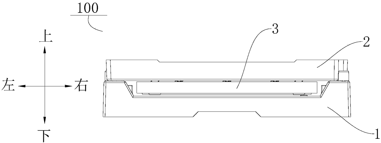
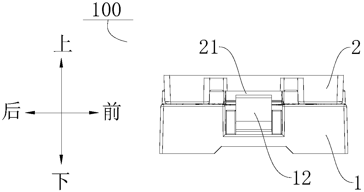
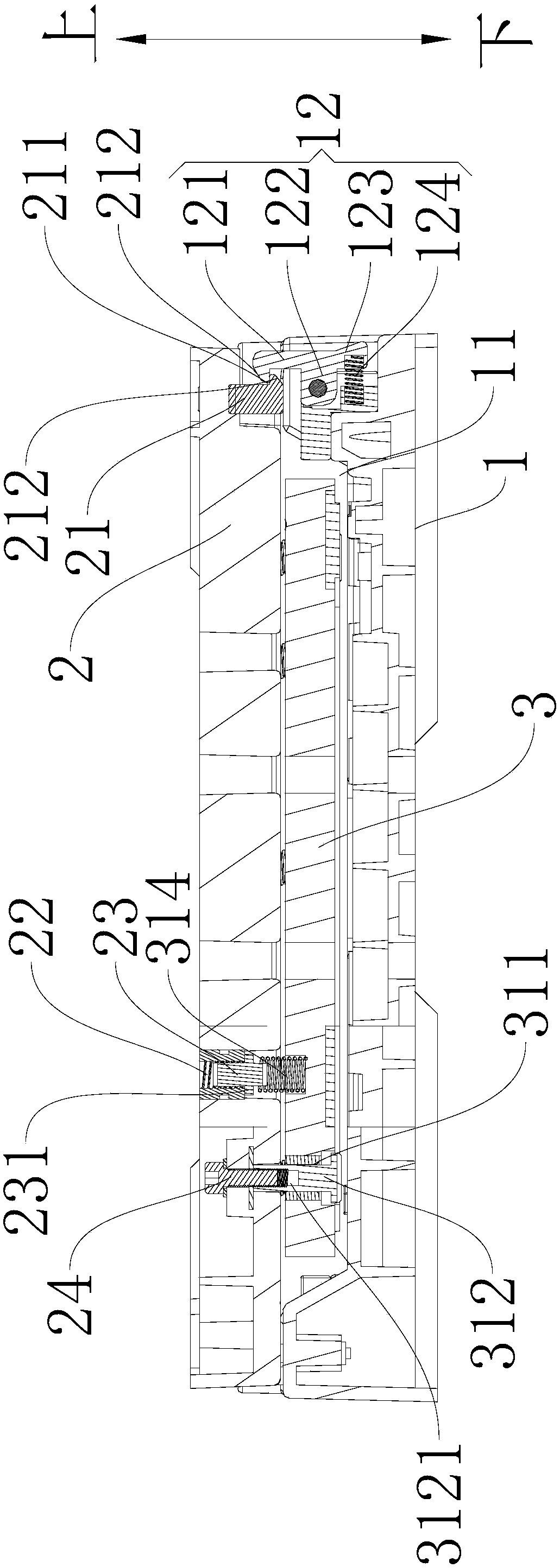
The invention discloses a pressure maintaining jig for an electronic device screen. The pressure maintaining jig for the electronic device screen comprises a pressure maintaining lower cover, a pressure maintaining upper cover, and a pressing plate assembly, wherein a holding groove for placing a shell to which a screen is attached is formed in the pressure maintaining lower cover; a first clamping piece is arranged on the pressure maintaining lower cover, and is a metal piece; the pressure maintaining upper cover is arranged on the pressure maintaining lower cover; a second clamping piece matched with the first clamping piece is arranged on the pressure maintaining upper cover, and is a metal piece; the pressing plate assembly is located between the pressure maintaining upper cover and the pressure maintaining lower cover; and the pressing plate assembly is connected with the pressure maintaining upper cover and is used for pressing the screen, so that the screen is pressed and attached onto the shell. According to the pressure maintaining jig for the electronic device screen, a pressure maintaining effect of the screen can be improved, the screen is prevented from loosening or upwarping, and the maintenance cost and the material loss are reduced. In addition, the service life of the pressure maintaining jig can be prolonged, and the pressure maintaining intensity of the pressure maintaining jig can be improved.

Description

technical field [0001] The invention relates to the field of manufacturing electronic equipment, in particular to a pressure-holding jig used for the screen of an electronic device. Background technique [0002] In the related art, the pressure holding fixture used for the screen of an electronic device is mainly a two-plate structure. The upper and lower covers of the two-plate structure are easily deformed, resulting in pressure imbalance, which may easily cause some parts of the screen to not be tightly pressed, and the screen is loose or cracked. warped phenomenon. In addition, the tooling hooks in the related art are easy to wear and have a short service life, and the overall pressure holding force of the pressure holding fixture is not enough and the reliability is poor. Contents of the invention [0003] The present invention aims to solve at least one of the technical problems existing in the prior art. Therefore, the present invention proposes a pressure-holding...

Claims


Application Information

Patent Timeline
Patent Type & Authority Applications(China)
IPC IPC(8): B25B11/00F16B11/00
CPCB25B11/00F16B11/006
Inventor 陈传江龚俊波
Owner GUANGDONG OPPO MOBILE TELECOMM CORP LTD
Learn More