Multipurpose electromagnetic valve and water purifier system consisting of same

A technology of solenoid valves and valve seats, applied in multi-way valves, valve devices, mechanical equipment, etc., can solve the problems of water resource waste, etc., and achieve the effects of prolonging flushing time, improving pressure holding effect, and saving water resources

Inactive Publication Date: 2012-10-03
吴瑞昌
View PDF5 Cites 2 Cited by
  • Summary
  • Abstract
  • Description
  • Claims
  • Application Information

AI Technical Summary

Problems solved by technology

When the existing pure water machine system flushes the reverse osmosis filter group, t

Method used


Image

  • Multipurpose electromagnetic valve and water purifier system consisting of same
  • Multipurpose electromagnetic valve and water purifier system consisting of same
  • Multipurpose electromagnetic valve and water purifier system consisting of same

Examples


Embodiment 1

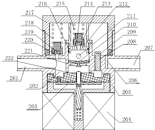
[0018] Such as figure 1 As shown, the multi-purpose solenoid valve includes a valve seat 205 and a valve seat cover 217 sealingly connected with the valve seat 205. The valve seat 205 is provided with a flushing and drainage inlet 201, a concentrated water discharge port 207, a flushing return water port 108, and a concentrated water discharge port. 207 is connected with the concentrated water discharge pipe 107, and the valve seat 205 is provided with a water inlet chamber 202 connected to the flushing and drainage inlet 201 and a flushing backflow channel 211 connected to the flushing backflow water port 108, and the valve seat 205 and the valve seat cover 217 constitute There is a concentrated water outlet chamber, and the concentrated water outlet chamber is connected to the concentrated water outlet 207 through the concentrated water flow channel 206 formed by the valve seat 205 . Both the flushing backflow channel 211 and the concentrated water outlet chamber are connect...

Embodiment 2

[0021]This embodiment adds the following structure on the basis of Embodiment 1: the valve seat 205 forms a pressure relief sealing port 220 connected to the water inlet chamber 202 and the concentrated water outlet chamber, and the concentrated water outlet chamber is provided with a pressure relief spring 2 218 and pressure relief seal seat 2 219, pressure relief seal seat 2 219 seals pressure relief seal water port 2 220, the two ends of pressure relief spring 2 218 act on valve seat cover 217 inner top and pressure relief seal seat 2 219 respectively, release The pressure spring 2 218 and the pressure relief seal 2 219 constitute the pressure relief assembly 2 that controls the switching of the water path between the water inlet chamber 202 and the concentrated water outlet chamber in on and off states. The valve seat 205 is connected with a choke rod 209, and a choke channel 208 connecting the water inlet chamber 202 and the concentrated water outlet chamber is formed betw...

Embodiment 3

[0023] This embodiment adds the following structure on the basis of Embodiment 1 or Embodiment 2: the valve seat 205 is connected with a pressure relief water sealing plate 212, and a sealing ring 216 is arranged between the valve seat 205 and the pressure relief water sealing plate 212. The pressure sealing water plate 212 is formed with a pressure relief sealing water port 213 connecting the flushing return flow channel 211 and the concentrated water outlet chamber. The concentrated water outlet chamber is provided with a pressure relief seal seat 214 and a pressure relief spring 1 215. Seat one 215 seals the pressure relief sealing water port one 213, and the two ends of the pressure relief spring one 215 respectively act on the inner top of the valve seat cover 217 and the pressure relief seal seat one 214, and the pressure relief seal seat one 214 and the pressure relief spring one 215 form a control valve. Pressure relief component 1 that switches between the water path b...


PUM


Abstract

The invention discloses a multipurpose electromagnetic valve, which comprises a valve seat and a valve seat sealing cover hermetically connected with the valve seat. The valve seat is provided with a flushing water discharge inlet, a concentrate water discharge opening and a flushing recirculation water opening; a water inlet cavity communicated with the flushing water discharge inlet and a flushing recirculation flow passage communicated with the flushing recirculation water opening are arranged in the valve seat; and the valve seat and the valve seat sealing cover form a concentrate water outlet cavity communicated with the concentrate water discharge opening. The flushing recirculation flow passage and the concentrate water outlet cavity are both communicated with the water inlet cavity, and a water sealing assembly controlling a waterway between the water inlet cavity and the flushing recirculation flow passage to be switched in an on state and an off state is arranged on the waterway of the water inlet cavity, which is communicated with the flushing recirculation flow passage. The invention also discloses a water purifier system consisting of the multipurpose electromagnetic valve; when the multipurpose electromagnetic valve adopting the above structure is applied to the water purifier system and when a reverse osmosis filtration assembly is flushed, flushing water can be utilized circularly, and water resources are saved.

Description

technical field [0001] The invention relates to a water cut-off device and a water treatment system constituted thereof, in particular to a multi-purpose electromagnetic valve and a pure water machine system constituted thereof. Background technique [0002] During the water production process of the pure water machine system, the concentrated water is discharged from the concentrated water outlet of the reverse osmosis filter group. Because the concentrated water is often accompanied by some impurities, some impurities will stay in the reverse osmosis filter group. Repeated water production in the pure water machine system During the process, there will be more and more impurities staying in the reverse osmosis filter group, which will affect the quality of purified water produced by the water purifier system. In order to ensure the purity of the water produced by the pure water machine system, people often flush the reverse osmosis filter group of the household pure water ...

Claims


Application Information

Patent Timeline
IPC IPC(8): F16K11/10C02F9/02C02F1/44
Inventor 吴瑞昌
Owner 吴瑞昌
Why Eureka
Try Eureka