Log shredding device for papermaking

A shredding device and log technology, applied in the direction of manufacturing tools, wood processing appliances, etc., can solve the problems of time-consuming, labor-intensive, slow shredding, uneven shredding, etc.

Active Publication Date: 2020-08-14
台州玉釉新材料科技有限公司
View PDF7 Cites 0 Cited by
  • Summary
  • Abstract
  • Description
  • Claims
  • Application Information

AI Technical Summary

Problems solved by technology

[0004] In order to overcome the disadvantages of time-consuming and labor-intensive chopping, uneven chopping, and slow chopping speed when manually chopping logs, the technical problem of the present invention is to provide a log for papermaking that is time-saving, labor-saving, evenly chopped, and fast chopping speed. shredding device

Method used


Image

  • Log shredding device for papermaking
  • Log shredding device for papermaking
  • Log shredding device for papermaking

Examples


Embodiment 1

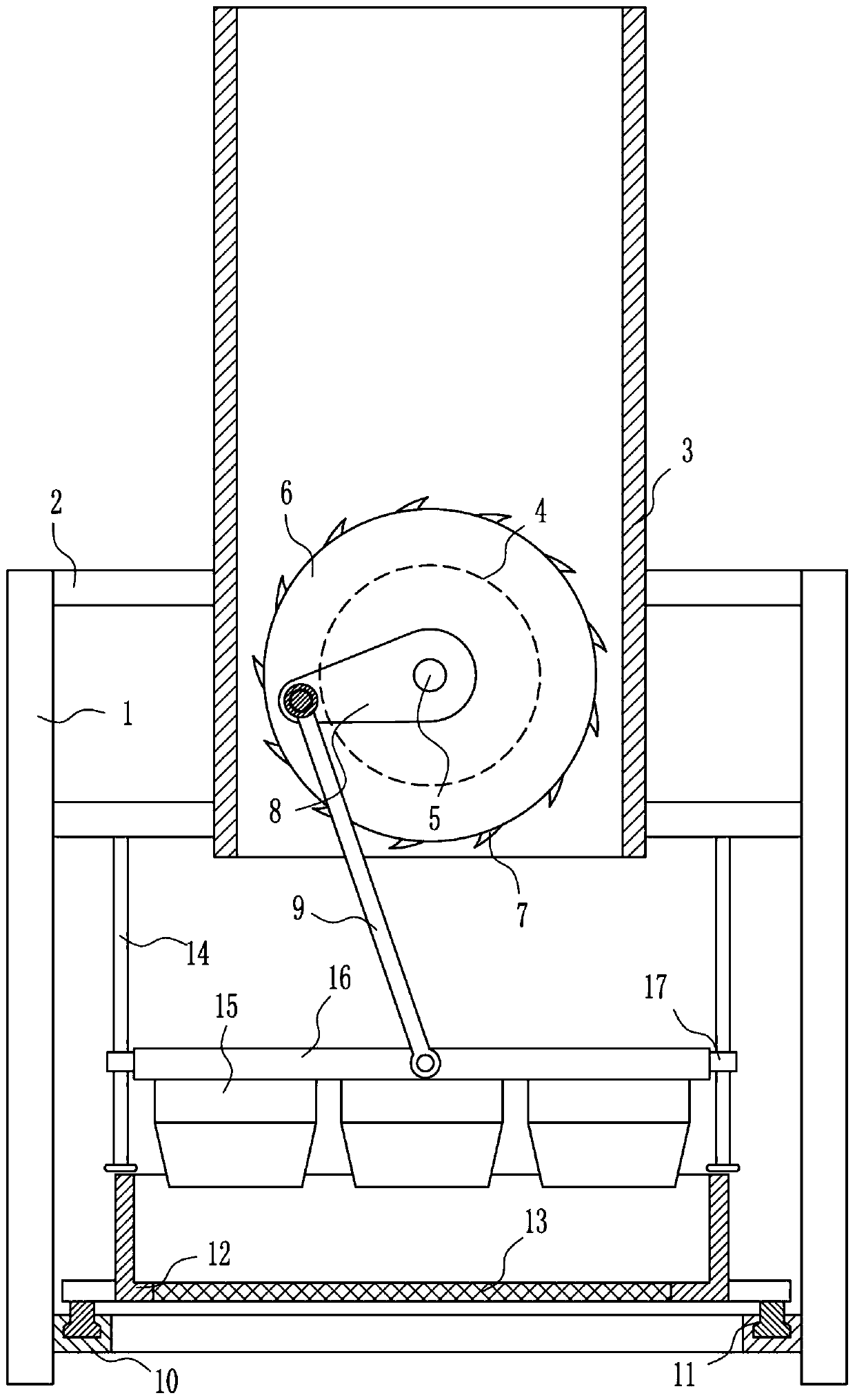
[0025] A log shredding device for papermaking, such as Figure 1-6 As shown, it includes a leg 1, a cross bar 2, a cylinder 3, a first motor 4, a rotating shaft 5, a drum 6, a planer 7, a movable block 8, a connecting rod 9, an annular slide rail 10, an annular slider 11, Frame body 12, screen plate 13, guide rod 14, cutter 15, horizontal plate 16 and guide sleeve 17, horizontal rods 2 are symmetrically installed on the inner sides of the left and right sides of the legs 1, and the inner ends of the four horizontal rods 2 A cylinder 3 is installed between them, and a rotating shaft 5 is installed between the lower part of the inner rear side of the cylinder 3 and the lower part of the front side in a rotating manner. The drum 6 is installed on the rotating shaft 5, and the planer 7 is installed on the outer surface of the drum 6 at even intervals. A movable block 8 is installed on the front end of the rotating shaft 5, and the movable block 8 is located on the outside of the c...

Embodiment 2

[0027] A log shredding device for papermaking, such as Figure 1-6 As shown, it includes a leg 1, a cross bar 2, a cylinder 3, a first motor 4, a rotating shaft 5, a drum 6, a planer 7, a movable block 8, a connecting rod 9, an annular slide rail 10, an annular slider 11, Frame body 12, screen plate 13, guide rod 14, cutter 15, horizontal plate 16 and guide sleeve 17, horizontal rods 2 are symmetrically installed on the inner sides of the left and right sides of the legs 1, and the inner ends of the four horizontal rods 2 A cylinder 3 is installed between them, and a rotating shaft 5 is installed between the lower part of the inner rear side of the cylinder 3 and the lower part of the front side in a rotating manner. The drum 6 is installed on the rotating shaft 5, and the planer 7 is installed on the outer surface of the drum 6 at even intervals. A movable block 8 is installed on the front end of the rotating shaft 5, and the movable block 8 is located on the outside of the c...

Embodiment 3

[0030] A log shredding device for papermaking, such as Figure 1-6 As shown, it includes a leg 1, a cross bar 2, a cylinder 3, a first motor 4, a rotating shaft 5, a drum 6, a planer 7, a movable block 8, a connecting rod 9, an annular slide rail 10, an annular slider 11, Frame body 12, screen plate 13, guide rod 14, cutter 15, horizontal plate 16 and guide sleeve 17, horizontal rods 2 are symmetrically installed on the inner sides of the left and right sides of the legs 1, and the inner ends of the four horizontal rods 2 A cylinder 3 is installed between them, and a rotating shaft 5 is installed between the lower part of the inner rear side of the cylinder 3 and the lower part of the front side in a rotating manner. The drum 6 is installed on the rotating shaft 5, and the planer 7 is installed on the outer surface of the drum 6 at even intervals. A movable block 8 is installed on the front end of the rotating shaft 5, and the movable block 8 is located on the outside of the c...


PUM


Abstract

The invention relates to a crushing device, in particular to a log crushing device for papermaking. The log crushing device for papermaking saves both time and labors, and is uniform in crushing and high in crushing speed. The log crushing device for papermaking comprises support legs, cross bars, a cylinder, a first motor, a rotating shaft, a roller, a planing head, a movable block, a connectingrod, an annular slide rail, an annular slide block, a frame body, a net plate, a guide rod and the like; the cross bars are symmetrically mounted at the upper parts of the inner side surfaces of the support legs on the left and right sides; the cylinder is mounted among inner ends of the four cross bars; the rotating shaft is rotationally mounted between the lower part of the back side surface andthe front side surface in the cylinder; and the roller is mounted on the rotating shaft. Through the effect of the planing head, logs can be firstly planed as log blocks, so that a cutter can preferably crush the logs; and through a pressing device, the influence on the block planing effect by movement of the logs can be prevented, so that the effects of time and labor saving, uniform crushing and high crushing speed are achieved.

Description

technical field [0001] The invention relates to a shredding device, in particular to a log shredding device for papermaking. Background technique [0002] Papermaking is an important invention of the working people in ancient China. There are two forms of mechanism and manual. The mechanism is carried out continuously on the paper machine. The pulp suitable for paper quality is diluted with water to a certain concentration, and is initially dehydrated in the wire part of the paper machine to form a wet paper sheet, which is then dehydrated by pressing, and then dried into paper. [0003] In the production process of papermaking, it is necessary to chop the peeled logs for the next step of processing. When manually chopping the logs, it is time-consuming, laborious, uneven, and slow, so there is an urgent need for research and development. The utility model relates to a paper-making log chopping device which saves time and effort, chops evenly, and has a high chopping speed...

Claims


Application Information

Patent Timeline
Patent Type & Authority Patents(China)
IPC IPC(8): B27L11/06
CPCB27L11/06
Inventor 叶财明杜娟郭才伟
Owner 台州玉釉新材料科技有限公司
Why Eureka
Try Eureka