Micro-liquid cooling device and method for automobile brake thermal decay

A technology of trace liquid and cooling device, which is applied in the direction of brakes, cooling brakes, vehicle parts, etc., can solve the problems of high working energy consumption and high cost of air-conditioning compressors, achieve cost reduction and working energy consumption, fast measurement, and avoid circuit problems Effect

Active Publication Date: 2018-09-28
CHANGAN UNIV
View PDF4 Cites 5 Cited by
  • Summary
  • Abstract
  • Description
  • Claims
  • Application Information

AI Technical Summary

Problems solved by technology

Air-conditioning compressor The air-conditioning compressor of t

Method used


Image

  • Micro-liquid cooling device and method for automobile brake thermal decay
  • Micro-liquid cooling device and method for automobile brake thermal decay
  • Micro-liquid cooling device and method for automobile brake thermal decay

Examples


Embodiment Construction

[0049] The present invention will be further described in detail below in conjunction with specific embodiments, which are explanations of the present invention rather than limitations.

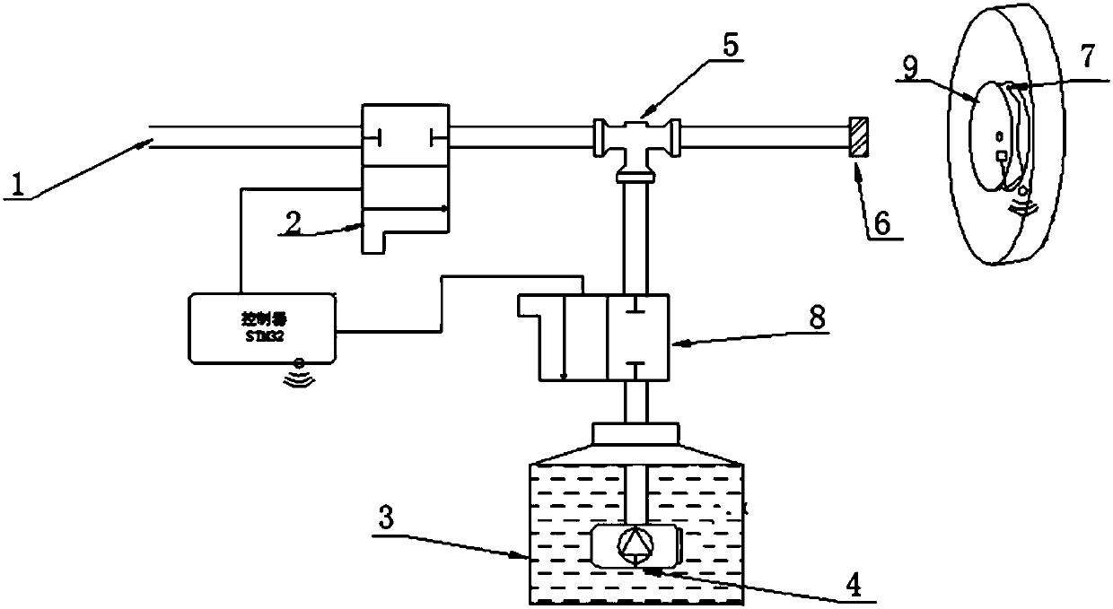
[0050] see figure 1 , the micro-liquid cooling device for automobile brake heat decay of the present invention, comprising a high-pressure gas access pipe 1, an air circuit switch valve 2, a tee 5, a nozzle 6, a water circuit switch valve 8, a water pump 4, a water tank 3, a controller and Temperature measuring element 7.

[0051] The gas circuit switch valve 2 is set on the high-pressure gas inlet pipe 1, and the output end of the high-pressure gas inlet pipe 1 is connected to one end of the tee 5, the second end of the tee 5 is connected to the nozzle 6, and the third end of the tee 5 is The water pump 4 is connected to the water pump 4 through the water circuit switch valve 8, and the water pump 4 is set in the water tank 3; when in use, the water is sprayed to the brake through the nozzl...


PUM


Abstract

The invention provides a micro-liquid cooling device and method for automobile brake thermal decay. Braking is unlikely to fail, the temperature is reduced stably, and energy consumption is low. The cooling device comprises a high-pressure gas connecting pipe, a gas circuit switching valve, a tee joint, a nozzle, a water way switching valve, a water pump, a water tank, a controller and a temperature measurement element. The gas circuit switching valve is arranged on the high-pressure gas connecting pipe, the output end of the high-pressure gas connecting pipe communicates with one end of the tee joint, the second end of the tee joint communicates with the nozzle, the third end of the tee joint communicates with the water pump through the water way switching valve, and the water pump communicates with the water tank. Both the gas circuit switching valve and the water way switching valve are connected with the controller, the temperature measurement element is used for acquiring a temperature signal of a brake and sending the temperature signal to the controller, and the controller controls the on-off states of the gas circuit switching valve and the water way switching valve according to the received temperature signal. Firstly, the temperature critical threshold value of the brake is calculated, and when the acquired temperature signal reaches the temperature critical thresholdvalue, the cooling device is started to cool the brake.

Description

technical field [0001] The invention belongs to the field of automobile cooling, and relates to a micro-liquid cooling device and method for heat decay of automobile brakes. Background technique [0002] During the long-term braking process of heavy-duty commercial vehicles, due to the friction between the brake drum and the brake of the vehicle brake, the brake will produce thermal degradation, which will lead to the failure of the vehicle brake and serious traffic accidents. If the car is going down a long slope, it must be braked for a long time, so the thermal recession of the brakes is inevitable. However, in winter, watering the brakes will cause the road to freeze, so the relevant laws prohibit the car from going down. Sprinkle water to cool down during the slope process. Therefore, the cooling of automobile brakes is an important part of the current commercial vehicle brake design. [0003] Existing cooling devices, wet brakes, brake spray cooling systems, and air-...

Claims


Application Information

Patent Timeline
IPC IPC(8): B60T5/00
CPCB60T5/00
Inventor 矫仟慧薛勇程涛于洋肖雄
Owner CHANGAN UNIV
Why Eureka
Try Eureka