
Loading and unloading equipment for automatic warehousing of goods

A loading and unloading equipment, automatic technology, applied in the direction of conveyor objects, transportation and packaging, etc., can solve the problems of low degree of automation, high use limitations, increased economic costs, etc., to improve the degree of automation, reduce economic costs, and improve practicability Effect

Inactive Publication Date: 2018-09-28
苏州奇思汇智能科技有限公司
View PDF0 Cites 5 Cited by
  • Summary
  • Abstract
  • Description
  • Claims
  • Application Information

AI Technical Summary

Problems solved by technology

[0002] As we all know, the loading and unloading equipment for automatic storage of goods is an auxiliary device used for loading and unloading incoming goods in the process of automatic storage system, so as to facilitate the better unloading of goods from trucks. It has been widely used in the field of automatic storage Use; the existing loading and unloading equipment for automatic storage of articles includes clamps, and the clamps are arranged at the cargo handling place; Move it out to the cargo transportation device at the warehouse door, and then continue to carry it; in the use of the existing loading and unloading equipment for automatic storage of items, it is found that manual use of clamps to clamp and release, wastes manpower, increases economic costs, and has poor practicability; and manual loading and unloading , the degree of automation is low, and the use limitations are high

Method used


Image

  • Loading and unloading equipment for automatic warehousing of goods
  • Loading and unloading equipment for automatic warehousing of goods

Examples


Embodiment Construction

[0016] The specific embodiments of the present invention will be described in further detail below in conjunction with the drawings and embodiments. The following examples are used to illustrate the present invention, but not to limit the scope of the present invention.

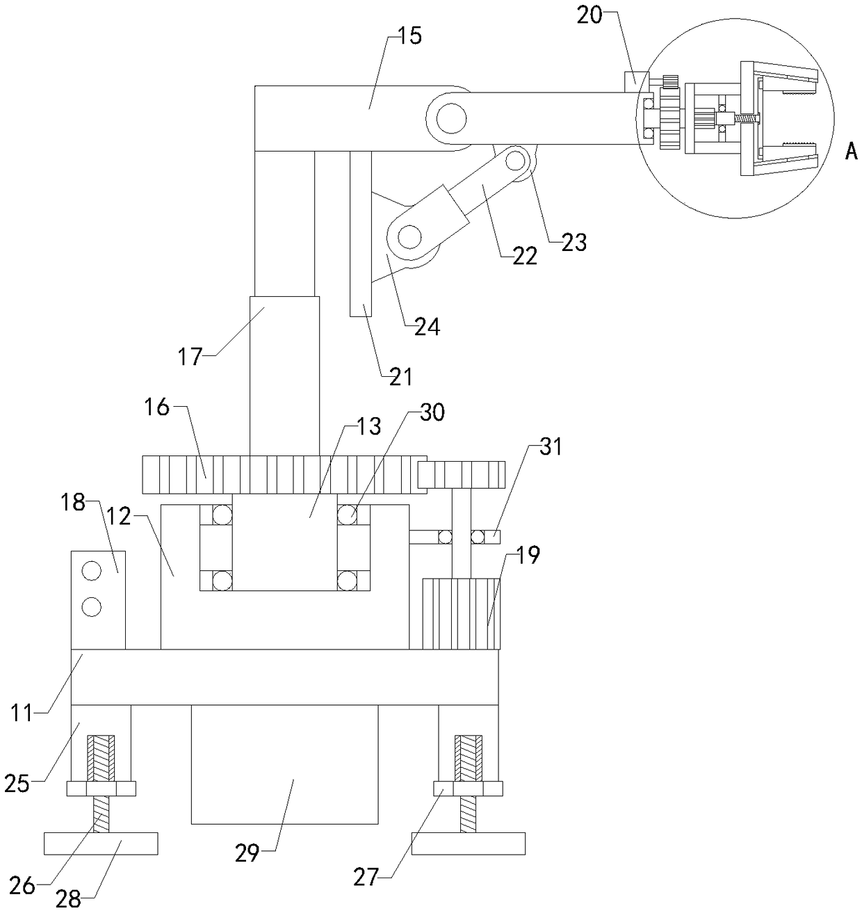
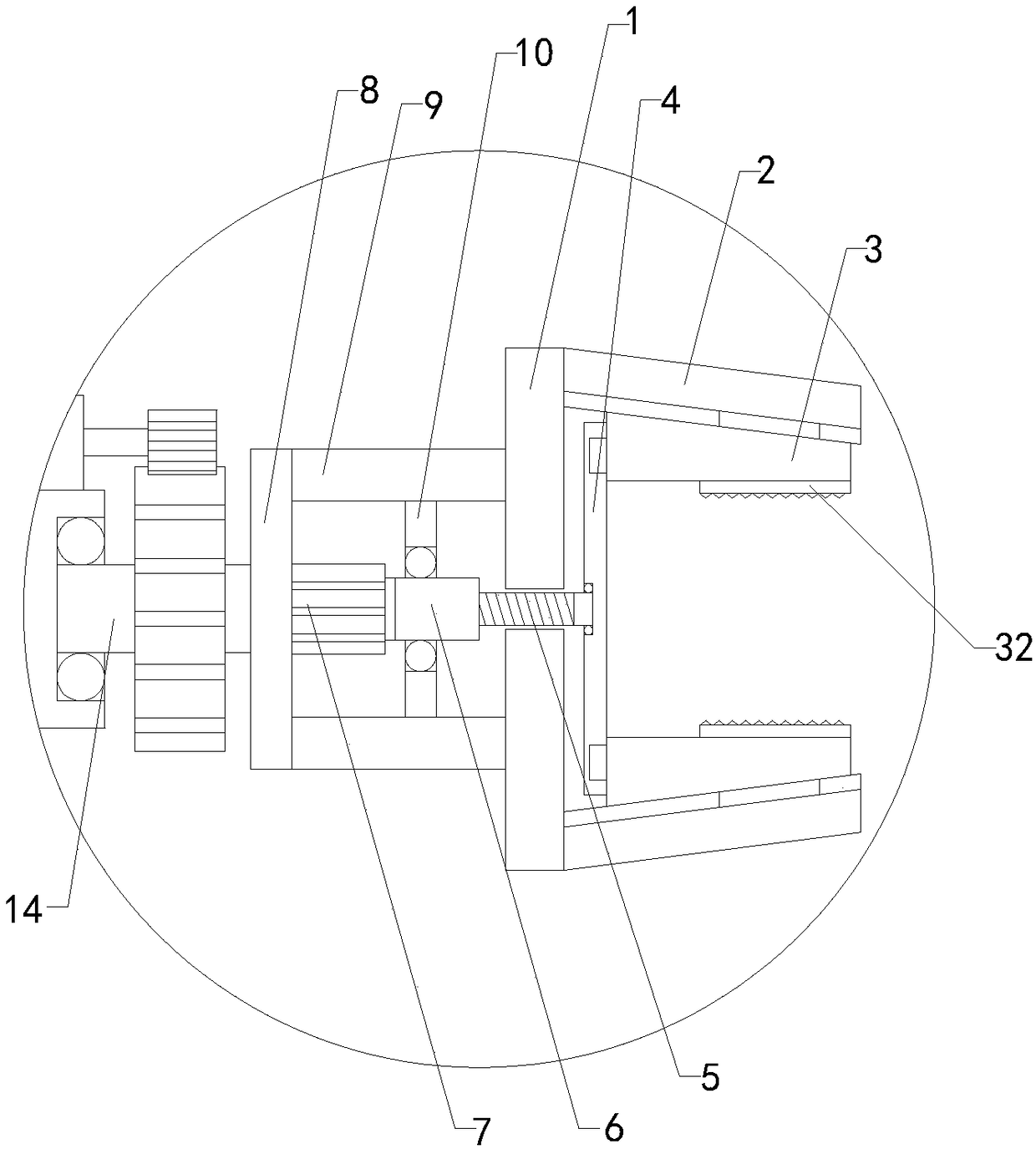
[0017] Such as Figure 1 to Figure 2 As shown, the loading and unloading equipment for automatic storage of articles of the present invention includes an operating panel 1, an upper clamping plate 2, a lower clamping plate, an upper clamping plate 3, a lower clamping plate, an adjusting plate 4, a threaded rod 5, and a threaded tube 6. , Adjustment motor 7, left baffle 8, upper baffle 9, lower baffle and fixed plate 10. The left ends of the upper and lower plates are respectively connected to the upper and lower sides of the right end of the operating panel, and the upper plate The bottom end is provided with an upper sliding groove, the top of the upper clamping plate is provided with an upper sliding block, t...


PUM


Abstract

The invention relates to the technical field of automatic warehousing accessory devices, in particular to loading and unloading equipment for automatic warehousing of goods. The loading and unloadingequipment can automatically clamp and release, saves manpower, reduces the economical cost, improves the practicality, increases the degree of automation and reduces the using limitation. The loadingand unloading equipment comprises an operating plate, an upper chuck plate, a lower chuck plate, an upper clamping plate, a lower clamping plate, an adjusting plate, a threaded rod, a threaded pipe, an adjustable motor, a left baffle plate, an upper baffle plate, a lower baffle plate and a fixed plate and further comprises a bottom plate, a placement block, a first rotary shaft, a second rotary shaft, a tumbler, a rotary table, a first electric cylinder, a controller, a first gear motor and a second gear motor, wherein the bottom end of the placement block is connected with the top end of thebottom plate; a first placement groove is formed in the top end of the placement block; a lower first placement ball bearing is arranged at the bottom end of the first placement groove; and the adjustable motor, the first gear motor, the second gear motor and the first electric cylinder are electrically connected with the controller.

Description

Technical field [0001] The invention relates to the technical field of automatic storage accessory devices, in particular to a loading and unloading equipment for automatic storage of goods. Background technique [0002] As we all know, the loading and unloading equipment for automatic storage of goods is an auxiliary device used for loading and unloading incoming goods in the process of automatic storage systems, so that the goods can be better unloaded from the truck. It has been widely used in the field of automatic storage. Use; the existing loading and unloading equipment for automatic storage of goods includes clamps, which are set in the cargo handling place; when the existing loading and unloading equipment for automatic storage of goods is used, first when the truck arrives, open the truck door and manually use the clamp to remove the goods. Move out to the cargo transportation device at the entrance of the warehouse, and then continue to carry it; in the use of the exis...

Claims


Application Information

Patent Timeline
IPC IPC(8): B65G47/90
CPCB65G47/902B65G47/905
Inventor 谈有进
Owner 苏州奇思汇智能科技有限公司
Learn More