
Vertical guiding device for piling machine

A technology for guiding devices and piling machinery, which is applied in the direction of supporting devices, sheet pile walls, rotary drilling rigs, etc., and can solve problems such as drilling inclination, soil at the bottom hindering the placement of vertical guiding devices, and inability to vertically guide piling machinery, etc. , to achieve the effect of convenient use

Inactive Publication Date: 2018-09-28
YUNHEMAN WALKER TOYS CO LTD
View PDF0 Cites 3 Cited by
  • Summary
  • Abstract
  • Description
  • Claims
  • Application Information

AI Technical Summary

Problems solved by technology

[0004] The purpose of the present invention is to provide a vertical guiding device for pile-working machinery to solve the problem that the existing vertical guiding device proposed in the background technology cannot effectively guide the pile-working machinery vertically during use, resulting in the failure of the pile-working machinery. During vertical operation, the drilling hole may be inclined, causing the drilled hole to be inclined, which will cause the base column to incline during the subsequent grouting operation. The guide device is placed in the round hole, and the bottom soil may hinder the placement of the vertical guide device.

Method used


Image

  • Vertical guiding device for piling machine
  • Vertical guiding device for piling machine
  • Vertical guiding device for piling machine

Examples


Embodiment Construction

[0027] The following will clearly and completely describe the technical solutions in the embodiments of the present invention with reference to the accompanying drawings in the embodiments of the present invention. Obviously, the described embodiments are only some, not all, embodiments of the present invention. Based on the embodiments of the present invention, all other embodiments obtained by persons of ordinary skill in the art without making creative efforts belong to the protection scope of the present invention.

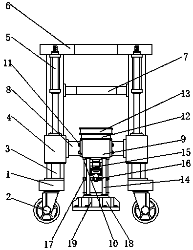
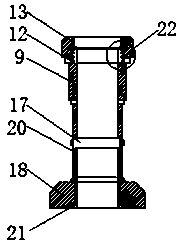
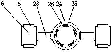
[0028] see Figure 1-6, the present invention provides a technical solution: including base 1, roller 2, slide rail 3, slider 4, hydraulic rod 5, top column 6, auxiliary rod 7, connecting column 8, cylinder body 9, fixing block 10, hexagonal screws 11. Fixed ring 12, upper pipe body 13, load-bearing rod 14, servo motor 15, gear 16, transmission gear 17, bottom cylinder 18, reinforcing rib 19, inner cylinder 20, grinding wheel 21, internal thread 22, fixed colu...


PUM


Abstract

The invention relates to a vertical guiding device for a piling machine. The vertical guiding device comprises a base, sliding blocks and a top post. Rolling wheels are connected to the lower end of the base. Sliding rails are arranged at the upper ends of the rolling wheels. The sliding blocks are distributed in the middles of the outer sides of the corresponding sliding rails. Hydraulic rods arecorrespondingly embedded into the tops of the sliding blocks. The top post is fixedly arranged on the tops of the sliding rails. An auxiliary rod is connected to the middle of the inner side of eachsliding rail. According to the vertical guiding device for the piling machine, through the arrangement of the base, the sliding rails and the top post, the base, the sliding rails and the top post form a structure in the shape like a Chinese character 'ji', and the base, the sliding rails and the top post are welded, so that the base, the sliding rails and the top post have good stability, the situation that the base, the sliding rails and the top post are unstably fixed, consequently collapse occurs among the base, the sliding rails and the top post, and the vertical guiding device cannot beeffectively used is prevented, and meanwhile a cylinder body is ensured to be vertically placed during use.

Description

technical field [0001] The invention relates to the technical field of pile machinery, in particular to a vertical guide device for pile machinery. Background technique [0002] Pile machinery refers to the machinery used for drilling, driving, and sinking piles in various pile foundation constructions. Pile machinery generally consists of two parts: a pile hammer and a pile frame. In addition to special pile frames, pile frames can also be set on excavators or cranes to complete piling tasks. The main characteristics of pile machinery are strong specificity and small production batches. According to the power source of the pile hammer movement of the pile driver, there are Drop hammer, steam hammer, diesel hammer, hydraulic hammer, etc. The pile driver is a machine that uses static force to push the pile top to make the pile penetrate into the ground. According to its pressurization mechanism, it can be divided into two types: mechanical type and hydraulic type. The self-w...

Claims


Application Information

Patent Timeline
Patent Type & Authority Applications(China)
IPC IPC(8): E02D13/04E21B3/02E21B7/02E21B15/00E21B19/086
CPCE02D13/04E21B3/02E21B7/02E21B15/00E21B19/086
Inventor 王婷
Owner YUNHEMAN WALKER TOYS CO LTD
Learn More