Double-backup unlocked U-shaped lock
A dual-backup, U-shaped technology, applied in padlocks, building locks, cylinder locks, etc., can solve the problems of poor structural strength, insufficient anti-pick ability, inconvenient operation, etc., to improve reliability and defense technology unlocking And the ability of anti-pick lock, the effect of improving the service life
- Summary
- Abstract
- Description
- Claims
- Application Information
AI Technical Summary
Problems solved by technology
Method used
Image
Examples
Embodiment 1
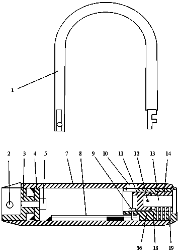
[0020] figure 1 ; U-shaped lock overall structure diagram.
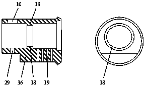
[0021] A rear fixing plate (4) is welded in the rear section of the long lock sleeve (7), the lock hook (1) is assembled on the lock hook seat (3) with the lock hook shaft (2), and then the lock hook seat (3) Assemble the screw (5) on the left end of the long lock sleeve (7), the lock hook shaft (2) is completely enclosed in the long lock sleeve (7), and has strong anti-prying ability. Weld a The lower fixed plate (8), the lower fixed plate (8) is provided with the installation hole of the lock body screw (9), and the inner ring (18) is arranged in the lock core hole of the lock body (36), see figure 2 , the rotary lock tongue (11) enters from the left end of the lock body (36), the lock cylinder (13) and sleeve core (14) enter from the other end of the lock body (36), the rotary lock tongue (11) and the lock cylinder (13 ) is connected with a connecting pin (12) to become a lock assembly. This lock assembly is ex...
Embodiment 2
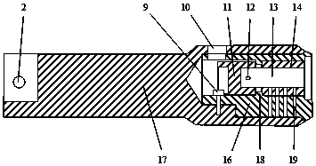
[0025] image 3 : the internal structure diagram of the U-shaped lock of combination lock sleeve (17).
[0026] The combination lock sleeve (17) is a combination of the lock hook seat (3) and the long lock sleeve (7), the installation hole of the lock hook shaft (2) is a blind hole, and the lock hook (1) is assembled with the lock hook shaft (2) on combination lock sleeve (17). The bottom of combined lock sleeve (17) is provided with installation hole, and lock body screw (9) enters from lock hole (10), and can enter the blind hole of combined lock sleeve (17) bottom, and lock body (16) is installed on In the combination lock sleeve (17), the double backup opening lock end assemblies are all assembled in the combination lock sleeve (17).
[0027] Figure 4 : the sectional view of lock body (16).
[0028] The lock body (16) is made up of two non-concentric cylinders, one large and one small. In this embodiment, the diameter of the small cylinder at the front end of the lock...
Embodiment 3
[0032] Figure 6 ; The internal structure diagram of the U-shaped lock of the combined lock body (26).
[0033] Combination lock body (26) is the combination of lock hook seat (3) and lock body (36), the mounting hole of lock hook shaft (2) is a blind hole, lock hook (1) is assembled on the lock hook shaft (2) on the combination lock body (26). The rotary lock tongue (11) and the lock cylinder (13) are connected with the connecting pin (12), so that the rotation lock tongue (11), the fixed ring (28), the lock cylinder (13), and the sleeve cylinder (14) are combined into a lock cylinder combination Parts, then assembled in the combined lock body (26) with set screws (15). The installation hole of set screw (15) is also the access hole of coupling pin (12), and the effect of fixed ring (28) and inner ring (18) is identical, and lock core assembly can't deviate from combination lock body (26). The following of the lock sleeve (27) is provided with a fixing hole, and the lock b...
PUM
| Property | Measurement | Unit |
|---|---|---|
| Diameter | aaaaa | aaaaa |
| Diameter | aaaaa | aaaaa |
Abstract
Description
Claims
Application Information
 - R&D
- Intellectual Property
- Life Sciences
- Materials
- Tech Scout
- Unparalleled Data Quality
- Higher Quality Content
- 60% Fewer Hallucinations
Browse by: Latest US Patents, China's latest patents, Technical Efficacy Thesaurus, Application Domain, Technology Topic, Popular Technical Reports.
© 2025 PatSnap. All rights reserved.Legal|Privacy policy|Modern Slavery Act Transparency Statement|Sitemap|About US| Contact US: help@patsnap.com


