Piston type air compressor, motion conversion mechanism and vehicle air compressor

A technology of piston movement and piston type, which is applied in the field of air compressors to achieve the effects of enhanced structural balance performance, excellent balance performance, and increased displacement

Pending Publication Date: 2018-09-28
中清能(北京)科技有限公司
View PDF11 Cites 0 Cited by
  • Summary
  • Abstract
  • Description
  • Claims
  • Application Information

AI Technical Summary

Problems solved by technology

[0004] The present invention provides a piston air compressor to solve the above-mentioned problems of the piston air compressor

Method used


Image

  • Piston type air compressor, motion conversion mechanism and vehicle air compressor
  • Piston type air compressor, motion conversion mechanism and vehicle air compressor
  • Piston type air compressor, motion conversion mechanism and vehicle air compressor

Examples


Embodiment 1

[0035] The present embodiment is a piston air compressor with 8-cylinder double cross structure (or double X structure). Figure 4 and Figure 5 The schematic diagram of the structure of the piston air compressor of this embodiment is shown. In this embodiment, the piston compressor of this embodiment is mainly described in combination with its arrangement form, and the body, driving device and accessories of the compressor are not described. There are too many descriptions, and relevant parts can refer to existing piston compressors.

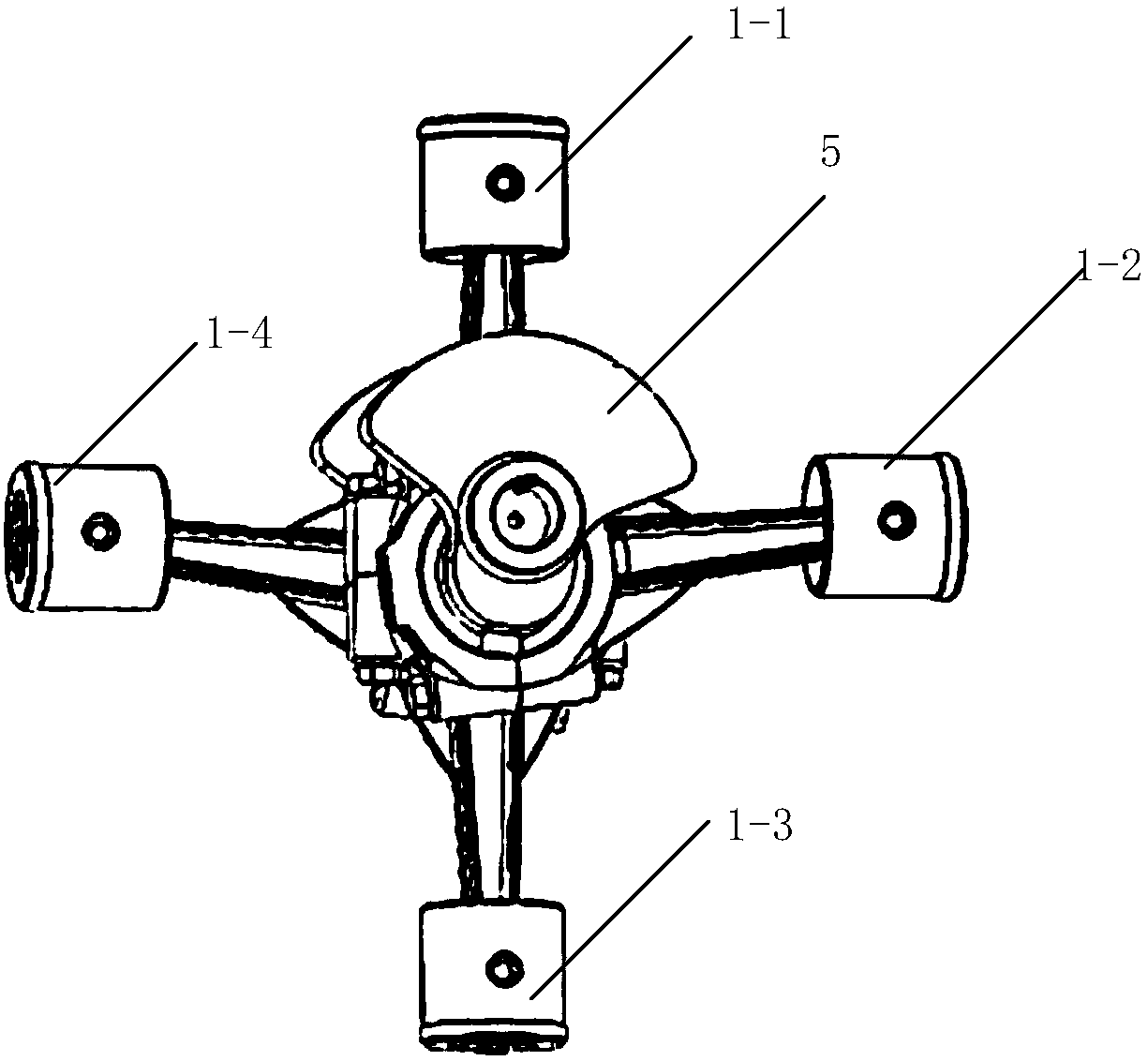
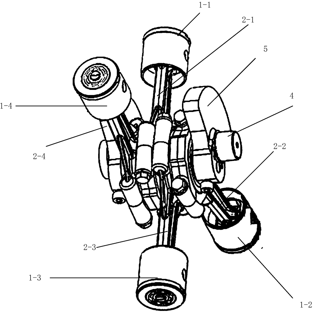
[0036] Please refer to Figure 4 and Figure 5 , the 8-cylinder double cross structure of this embodiment includes eight compression cylinders 20, which are placed on both sides of the compressor, four cylinders on one side, and the four cylinders on one side are arranged in a cross shape, and a driving device is arranged in the middle. In the example, the driving device is a driving motor 10 . The whole machine is arranged on the base 30 ....

Embodiment 2

[0042] The piston air compressor of this embodiment is the same as that of the first embodiment above, and is also an 8-cylinder double cross structure. block structure. Each rotary-reciprocating conversion mechanism includes four single-acting pistons and four round sliders, and the arrangement of the pistons is the same as in the first embodiment. An oil-free bearing can be used between the piston and the slider, and other structures of the piston air compressor in this embodiment can be the same as that of the first embodiment above, and will not be discussed here. The piston air compressor of this embodiment has the same technical effect as the above embodiment, and furthermore, the secondary reciprocating moment of inertia is also zero. Has a better balancing effect.

Embodiment 3

[0044] In this embodiment, the piston air compressor is a 4-cylinder cross-shaped structure, that is, a rotary reciprocating conversion device is used. The rotary reciprocating motion conversion device can adopt the structure of the above-mentioned embodiment 1 or the structure of the above-mentioned embodiment 2. Other aspects of the piston air compressor in this embodiment can be the same as the above-mentioned embodiment, and will not be discussed here.


PUM


Abstract

The invention discloses a piston type air compressor. The piston type air compressor comprises a machine body, a first rotary reciprocating motion conversion device, a second rotary reciprocating motion conversion device and a drive device, wherein the first rotary reciprocating motion conversion device and the second rotary reciprocating motion conversion device are the same in structure, and each rotary reciprocating motion conversion device comprises a single-throw crank shaft, and four pistons which are connected with a crank pin of the single-throw crank shaft, and the arrangement way, onthe crank pin, of the four pistons is as follows: the motion direction of the two pistons at the two sides and the motion direction of the pistons on the middle are arranged at an angle of 180 degrees, and the motion direction of the two pistons at the two sides is perpendicular to the motion direction of the pistons on the middle part; the first rotary reciprocating motion conversion device andthe second rotary reciprocating motion conversion device are arranged on the machine body; and crankshafts of the two rotary reciprocating motion conversion devices are connected with a drive shaft ofthe drive device. The invention further provides a rotary reciprocating motion conversion mechanism and a vehicle air compressor.

Description

[0001] This application claims the priority of the Chinese patent application submitted to the China Patent Office on March 23, 2017, the application number is 201720289774.X, and the invention name is "A Piston Air Compressor, a Motion Conversion Mechanism, and an Air Compressor for Vehicles" rights, the entire contents of which are incorporated in this application by reference. technical field [0002] The invention relates to the technical field of air compressors. Specifically relates to a piston type air compressor. Background technique [0003] At present, the mainstream air compressors used for vehicle braking mostly use a compressor assembly composed of two V-shaped twin-cylinder air compressors driven coaxially by a motor. For each V-type air compressor, a single-throw crankshaft is used. On the crankpin of the crankshaft, there are more than two pistons at an angle of 90 degrees to each other. The connection structure between the piston and the crankpin is a crank...

Claims


Application Information

Patent Timeline
Patent Type & Authority Applications(China)
IPC IPC(8): F04B27/053F04B39/00
CPCF04B27/0404F04B27/053
Inventor 蔡勇王清旭黎明
Owner 中清能(北京)科技有限公司
Why Eureka
Try Eureka