Conical air inducing machine
An inducer and cone-shaped technology, which is applied in the direction of machines/engines, non-displacement pumps, mechanical equipment, etc., can solve the problems of high energy consumption and easy damage of fans, and achieve the effect of improving air flow
- Summary
- Abstract
- Description
- Claims
- Application Information
AI Technical Summary
Problems solved by technology
Method used
Image

Examples
Embodiment 1
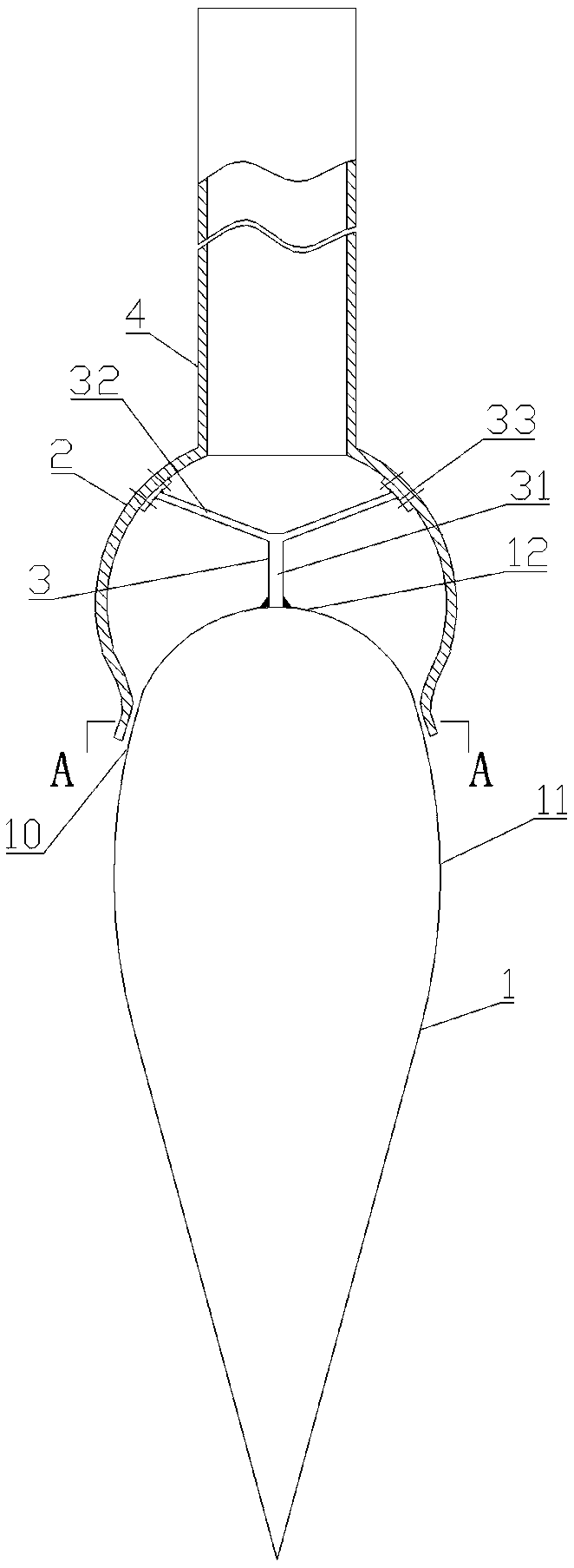
[0022] Such as figure 1 As shown, the conical air inducer includes a conical inducer 1, a spherical casing 2, a connecting frame 3 and an air intake pipe 4.
[0023] The conical inducer 1 is conical, with a Coanda curved surface 11 on its side wall, and a convex curved surface 12 on its bottom surface. The curved surface 12 and the Coanda curved surface 11 transition smoothly.
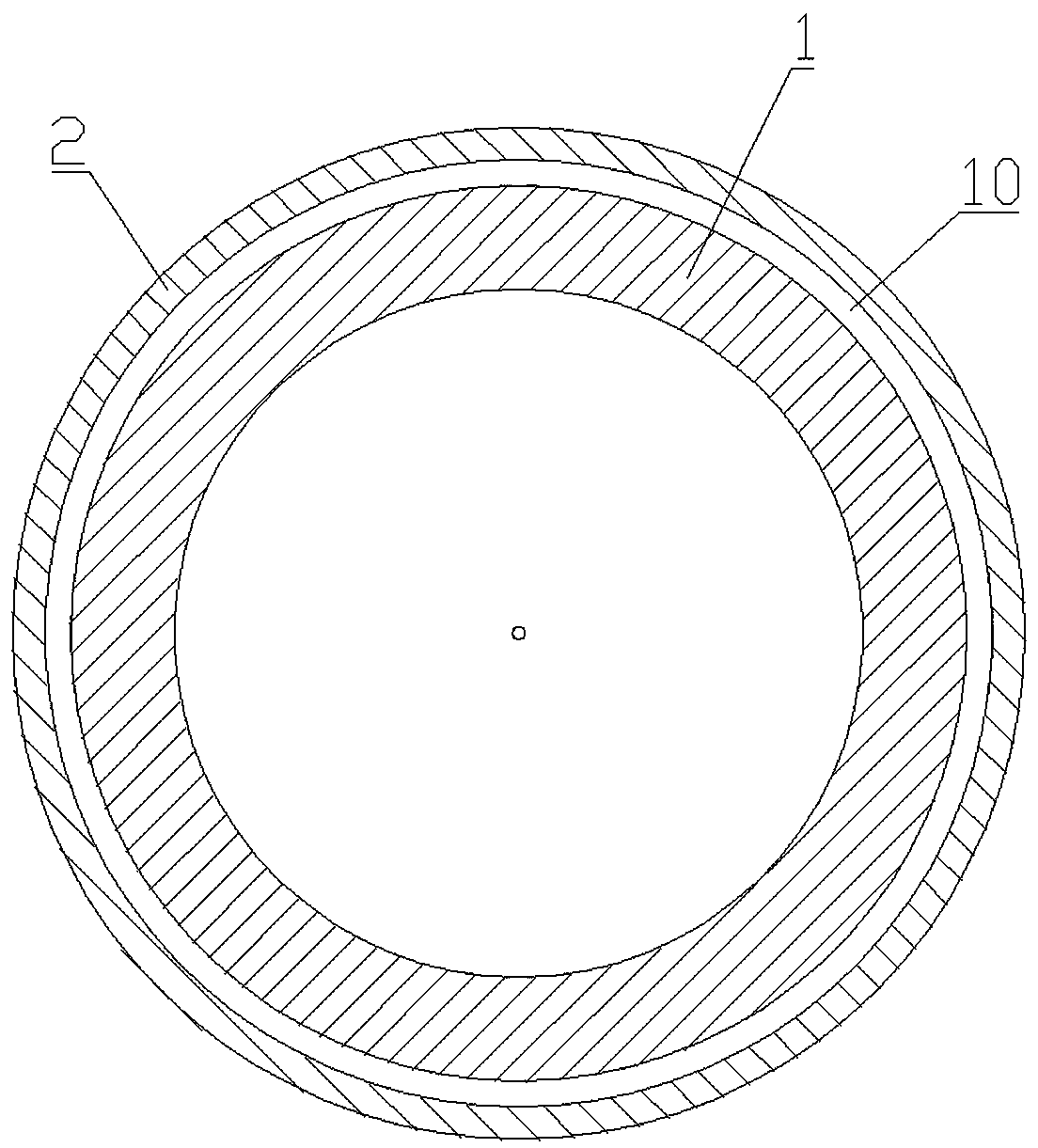
[0024] One end of the spherical case 2 is provided with an air inlet, and the other end is provided with an air outlet. The spherical case 2 is connected to the conical inducer 1 through a connecting frame 3, and its air outlet is facing the arc surface of the conical inducer 1, and is connected with the conical inducer 1. An annular air outlet 10 is formed between the conical inducers.
[0025] Connector 3 comprises main rod 31, branch rod 32 and connecting plate 33; A plurality of branch rods 32 are circularly evenly distributed around the center line of main rod 31 and welded on one end of main rod...
Embodiment 2
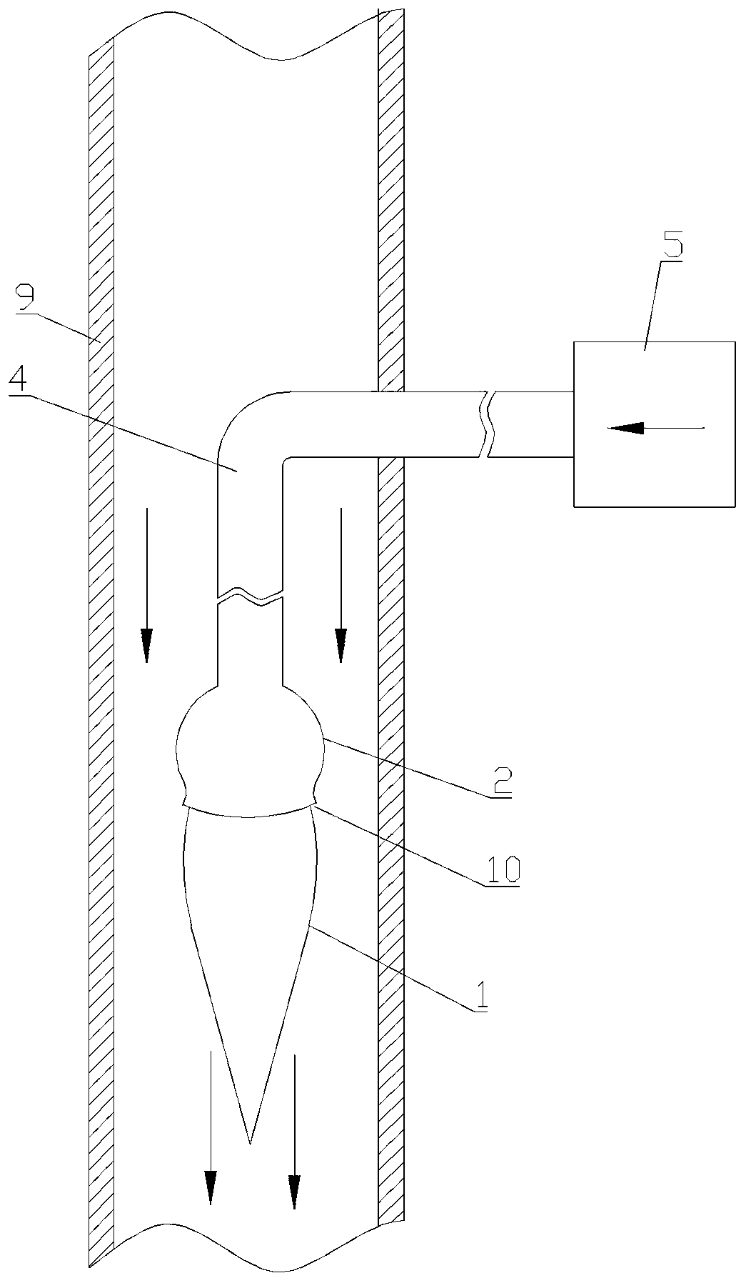
[0029] Such as Figure 4 As shown, the only difference between this embodiment and Embodiment 1 is that the conical air inducer also includes a fan 6, and the fan 6 is installed in the intake pipe 4 through a bracket.
[0030] In this embodiment, the intake pipe 4 can be designed as a straight pipe or a curved pipe according to actual needs. When the air intake pipe 4 is a straight pipe, it can be used independently as an air induction device. see Figure 5 , when the inlet pipe 4 is an elbow, it is used for gas drainage in the pipeline, the inlet end of the inlet pipe 4 bends and passes through the pipeline 9 walls, and the bending angle of the inlet pipe 4 is a, and a is 90°.
[0031] The principle of the present invention is: under the action of the fan or high-pressure air source, the gas enters the spherical casing 2 from the inlet pipe 4, and finally forms a high-speed air flow area at the air outlet 10; The negative pressure zone is created, so that the surrounding g...
PUM
 Abstract
Description
Claims
Application Information
 - Generate Ideas
- Intellectual Property
- Life Sciences
- Materials
- Tech Scout
- Unparalleled Data Quality
- Higher Quality Content
- 60% Fewer Hallucinations
Browse by: Latest US Patents, China's latest patents, Technical Efficacy Thesaurus, Application Domain, Technology Topic, Popular Technical Reports.
© 2025 PatSnap. All rights reserved.Legal|Privacy policy|Modern Slavery Act Transparency Statement|Sitemap|About US| Contact US: help@patsnap.com