Centrifugal speed regulator device for preventing pulsation

A technology of centrifugal speed governor and hydraulic cylinder, which is applied in transmission devices, transmission parts, fluid transmission devices, etc. It can solve problems such as excessive impact, different quality, and influence on the operation process, so as to reduce excessive impact and make it easy to use effect, the effect of eliminating vibration

Inactive Publication Date: 2018-09-28
狄文莉
View PDF0 Cites 3 Cited by
  • Summary
  • Abstract
  • Description
  • Claims
  • Application Information

AI Technical Summary

Problems solved by technology

[0002] At present, the existing centrifugal speed governor causes system pressure pulsation during operation, resulting in vibration and noise, excessive impact and problems affecting the operation process
By designing a centrifugal governor device that prevents pulsation and installing a corresponding device, during the manufacturing process of the traditional centrifugal governor, due to the uneven material density of the centrifugal ball, the quality of the centrifugal ball will be reduced. Different, or

Method used


Image

  • Centrifugal speed regulator device for preventing pulsation
  • Centrifugal speed regulator device for preventing pulsation
  • Centrifugal speed regulator device for preventing pulsation

Examples


Embodiment Construction

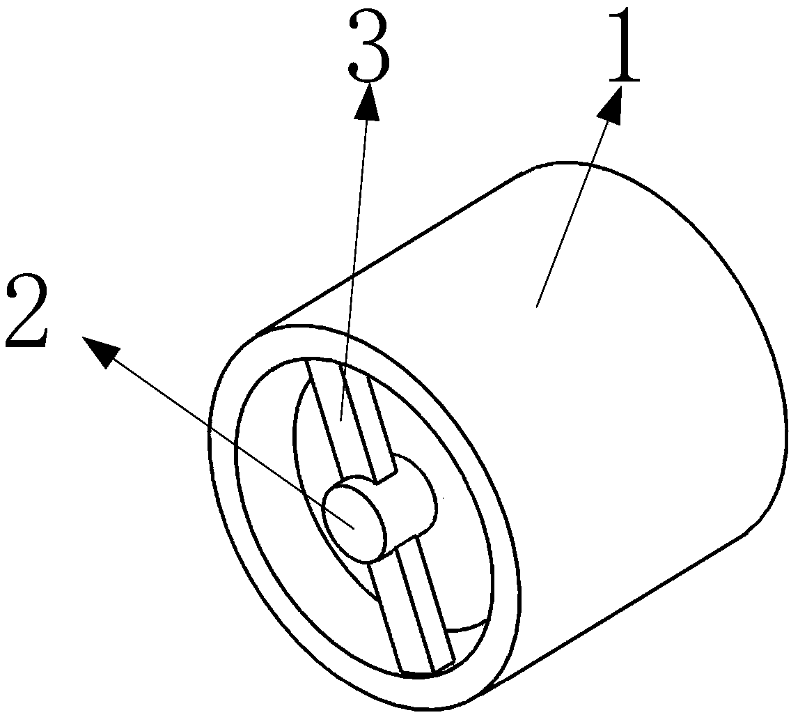
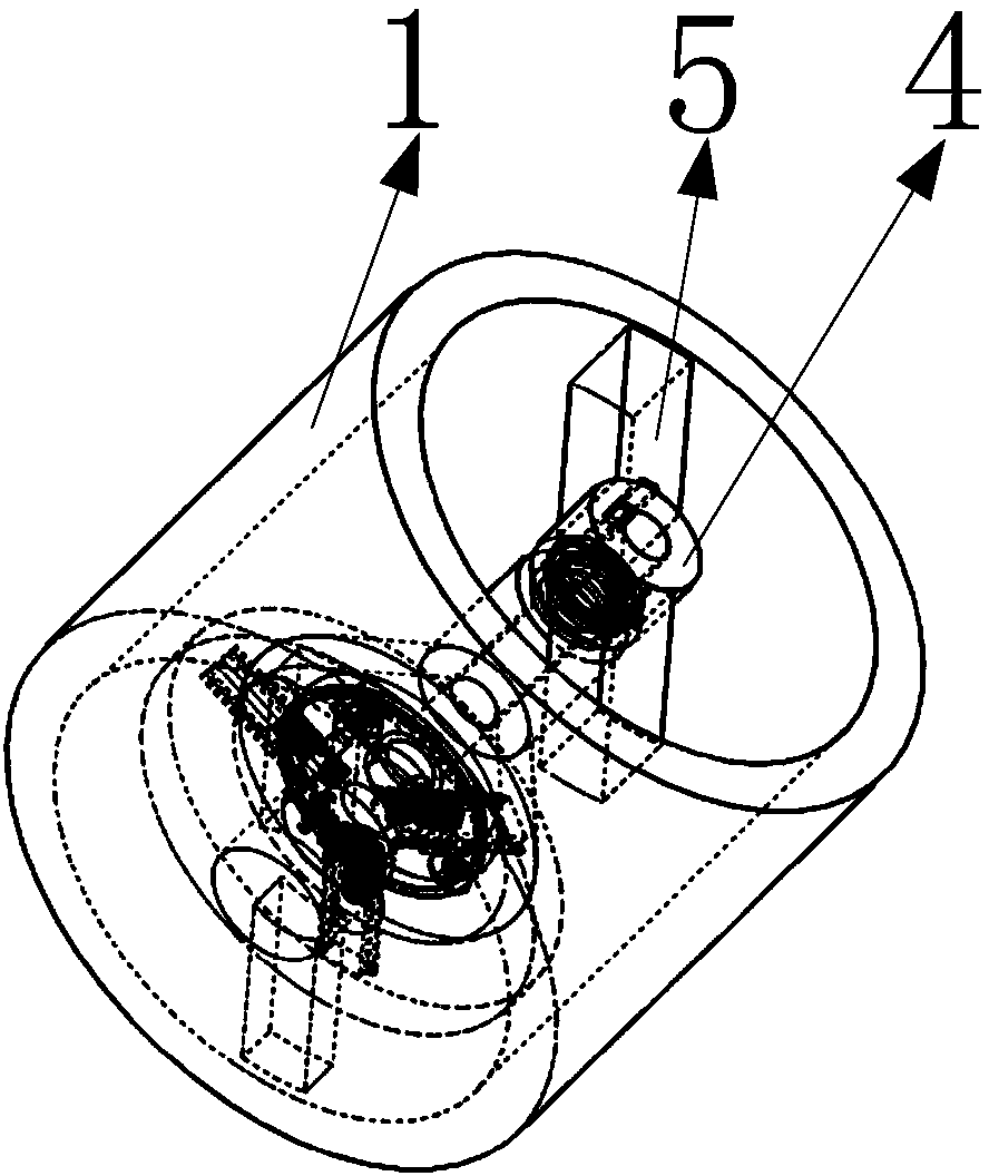
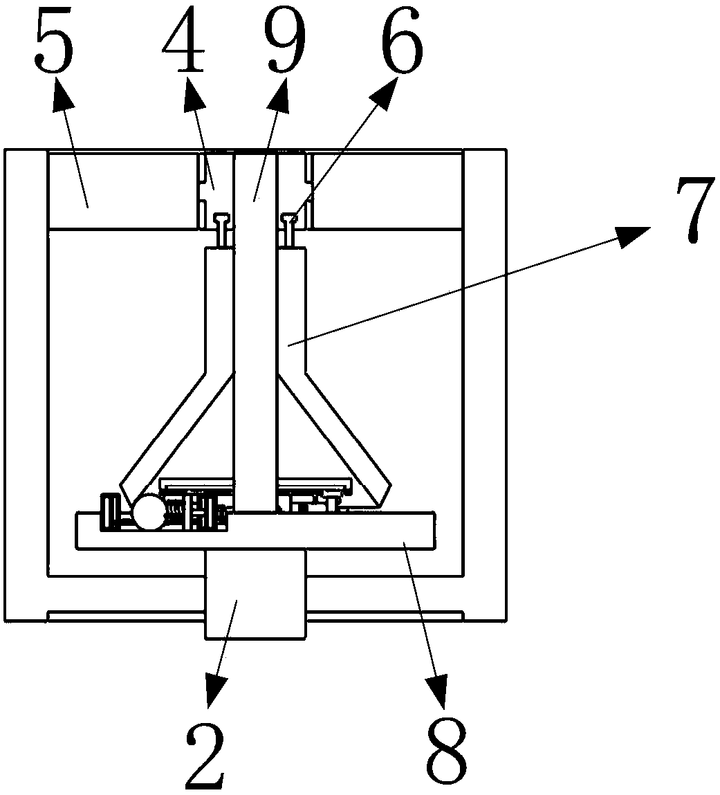
[0032] Such as figure 1 , 2 As shown, it includes a circular fixed shell 1, an input shaft 2, a first fixed column 3, a control rod 4, a second fixed column 5, a T-ring 6, a conical shell 7, a disc 8, a connecting shaft 9, a fixed Disk 10, first hydraulic cylinder 11, second hydraulic cylinder 12, third hydraulic cylinder 13, ring gear 14, guide block 15, rectangular groove 16, first ball 17, second ball 18, third ball 19, gear 20. The first fixed spring 21, the second fixed spring 22, the fixed block 23, the rack 24, the fixed plate 25, the fixed shaft 26, the fourth hydraulic cylinder 27, such as Figure 5 As shown, one end of the two first fixed columns 3 is fixedly installed on the inner circle surface of one end of the circular fixed shell 1; notches are arranged on the end faces of one end of the two second fixed columns 5; two second fixed columns 5 The end of the column 5 without a notch is fixedly installed on the inner circular surface of the circular fixed shell 1...


PUM


Abstract

The invention belongs to the technical field of centrifugal speed regulators, and particularly relates to a centrifugal speed regulator device for preventing pulsation. The centrifugal speed regulatordevice for preventing pulsation comprises an input shaft, a disc, fixed blocks, racks, a conical shell and a control rod, wherein the input shaft rotates and drives the disc to rotate; when the rotating speed of the disc is relatively fast, the three fixed blocks move and drive the three corresponding racks to move under the effect of the centrifugal force; the three racks move and drive three corresponding gears to rotate; the three gears rotate and drive an annular gear ring to rotate; three first fixed springs extrude three first hydraulic cylinders; at the moment, the conical shell suffers the acting force of a ball No.1, a ball No.2 and a ball No.3 under the combined action of the first fixed springs and the centrifugal force; and the ball No.1, the ball No.2 and the ball No.3 extrude the conical shell under the action of centrifugal force, and the conical shell moves axially at the moment, so that the conical shell suffers the same pressure force, and further the pulsation phenomenon happening to the centrifugal speed regulator is avoided.

Description

technical field [0001] The invention belongs to the technical field of centrifugal governors, in particular to a centrifugal governor device for preventing pulsation. Background technique [0002] At present, the existing centrifugal speed governor causes system pressure pulsation during operation, produces vibration and noise, excessive impact and problems affecting the operation process. By designing a centrifugal governor device that prevents pulsation and installing a corresponding device, during the manufacturing process of the traditional centrifugal governor, due to the uneven material density of the centrifugal ball, the quality of the centrifugal ball will be reduced. Different, or the quality is different due to the wear of the centrifugal ball; under the action of different masses of the centrifugal ball, the centrifugal force on the centrifugal ball will be different, so that the centrifugal ball will have different forces on the conical shell. At this time, the ...

Claims


Application Information

Patent Timeline
IPC IPC(8): F16H35/00F16H47/02F16H57/00
CPCF16H35/00F16H47/02F16H57/0006F16H2057/0012
Inventor 狄文莉
Owner 狄文莉
Why Eureka
Try Eureka