Heat dissipation device of LED lamp and LED lamp

A technology of LED lamps and heat dissipation devices, which is applied to the cooling/heating devices of lighting devices, lighting devices, lighting and heating equipment, etc., which can solve the problems of heat conduction failure, weak heat dissipation capacity, thick heat dissipation fins, etc., and achieve stable and efficient heat dissipation , Simple manufacture, strong heat conduction effect

Pending Publication Date: 2018-09-28
江苏泓睿德智能科技有限公司
View PDF0 Cites 0 Cited by
  • Summary
  • Abstract
  • Description
  • Claims
  • Application Information

AI Technical Summary

Problems solved by technology

[0004] At present, there are generally two types of heat sinks for LED lamps. One is an integrated heat sink that is directly die-cast. This heat sink has thicker fins and weaker heat dissipation due to the production process.
The other is to splice and assemble extruded metal thin-walled parts into a heat sink. This kind of heat sink has thinner fins and stronger heat dissipation capability. However, due to the deformation of metal thin-walled parts, it is easy to produce Poor contact leads to heat conduction failure in some positions

Method used


Image

  • Heat dissipation device of LED lamp and LED lamp
  • Heat dissipation device of LED lamp and LED lamp
  • Heat dissipation device of LED lamp and LED lamp

Examples


specific Embodiment approach 1

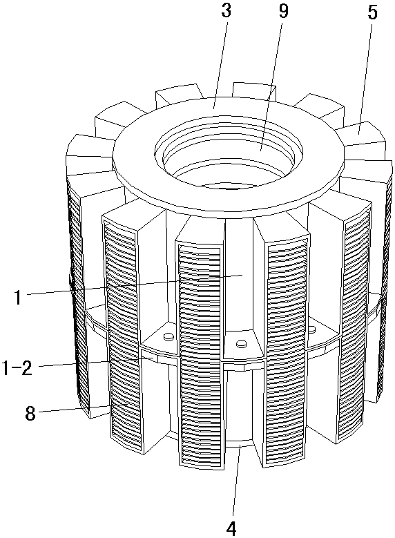
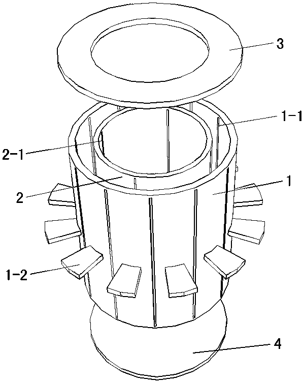
[0018] Specific implementation mode one: as Figure 1~Figure 6 As shown, the present invention discloses a LED lamp heat dissipation device, which includes a main body mounting shell, a lamp holder 9, two heat dissipation positioning members 5, a plurality of high thermal conductivity rectangular metal sheets 1 6, a plurality of high thermal conductivity rectangular metal sheets 2 7 and A plurality of heat dissipation fins 8, the main body installation shell includes an outer cylinder 1 and an inner cylinder 2 coaxially spaced apart, and the upper and lower ends of the outer cylinder 1 and the inner cylinder 2 respectively pass through The upper sealing ring 3 and the lower sealing plate 4 are bonded and fixed (the upper sealing ring 3 seals the outer cylinder 1 and the upper end of the inner cylinder 2 at intervals, and the lower sealing plate 4 seals all the lower ends of the outer cylinder 1 and the inner cylinder 2), Mercury is injected between the outer cylinder 1 and the...

specific Embodiment approach 2

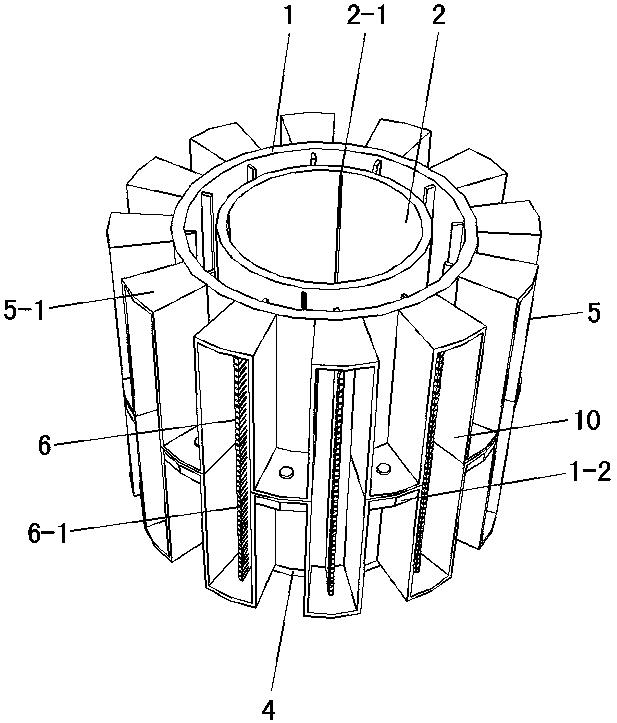
[0019] Specific implementation mode two: as figure 1 , 3 As shown, this embodiment is a further description of specific embodiment 1. The middle of the outer wall of the outer cylinder 1 is fixed with a plurality of positioning flaps 1-2 along the circumferential direction, and the plurality of positioning flaps 1-2 are 2 are clamped between every two adjacent mounting slots 10 one by one, and fixed to the corresponding positions of the two heat dissipation positioning members 5 by screws.

specific Embodiment approach 3

[0020] Specific implementation mode three: as figure 1 , 3 , 6, this embodiment is a further description of specific embodiment 1 or specific embodiment 2, and each of the high thermal conductivity rectangular metal sheets 6 is provided with a plurality of sockets 6-6 at vertical intervals. 1. The plurality of heat dissipation fins 8 are all provided with the second socket 8-1 matching the first socket 6-1, and the plurality of heat dissipation fins 8 pass through the second socket 8-1 respectively. It is inserted into the socket 1 6-1 corresponding to the high thermal conductivity rectangular metal sheet 1 6 .


PUM


Abstract

The invention discloses a heat dissipation device of an LED lamp and the LED lamp, and relates to the field of LED illumination. The heat dissipation device is characterized in that an outer cylinderand the inner cylinder are adhered and fixed to each other through an upper sealing ring and a lower sealing plate, mercury fills the space between the outer cylinder and the inner cylinder, and two heat dissipation positioning components are in butt joint and sleeve the exterior of the outer cylinder in a matched mode; a plurality of vertical notches I are formed in the cylinder wall of the outercylinder, the middles of a plurality of high-heat-conduction rectangular metal sheets I are fixedly and hermetically adhered to the interiors of the corresponding vertical notches I, the inner end ofeach high-heat-conduction rectangular metal sheet I extend into the position between the outer cylinder and the inner cylinder, and the outer end of each high-heat-conduction rectangular metal sheetI is provided with a plurality of heat dissipation fins in an inserted mode; a lamp holder is fixedly adhered to the inside of the inner cylinder, a plurality of vertical notches II are formed in thewall of the inner cylinder, the middles of a plurality of high-heat-conduction rectangular metal sheets II are fixedly and hermetically adhered to the interiors of the corresponding vertical notches II, the outer end of each high-heat-conduction rectangular metal sheet II extend into the position between the outer cylinder and the inner cylinder, and the inner end of each high-heat-conduction rectangular metal sheet II is tightly attached to the lamp holder. According to the heat dissipation device, the heat conduction transition is carried out through the mercury, and the heat dissipation isstable and efficient.

Description

technical field [0001] The invention relates to the field of LED lighting, in particular to an LED lamp cooling device and an LED lamp. Background technique [0002] In the field of lighting, LED lamps have basically replaced traditional tungsten lamps due to their advantages of energy saving, environmental protection and relatively long service life compared with traditional tungsten lamps. [0003] As we all know, LED lights will generate a lot of heat when they are used, especially high-power LED lights. If the heat generated cannot be discharged in time, it will affect the lighting effect of the LED lights and even shorten the service life. Therefore, the LED light cooling device role is particularly important. [0004] At present, there are generally two types of heat sinks for LED lamps. One is an integrated heat sink that is directly die-cast. This heat sink has thicker fins and weaker heat dissipation due to the production process. The other is to splice and assemb...

Claims


Application Information

Patent Timeline
Patent Type & Authority Applications(China)
IPC IPC(8): F21V29/76F21Y115/10
CPCF21V29/76F21Y2115/10
Inventor 付春明熊大曦廖新胜
Owner 江苏泓睿德智能科技有限公司
Why Eureka
Try Eureka