Novel LED lamp heat dissipation structure

A technology of LED lamps and heat dissipation structures, applied in lighting and heating equipment, cooling/heating devices of lighting devices, lighting devices, etc., can solve the problems of weak heat dissipation, heat conduction failure, thick heat dissipation fins, etc., and achieve stable and efficient heat dissipation , Avoid poor contact, strong heat conduction effect

Pending Publication Date: 2018-10-23
江苏泓睿德智能科技有限公司
View PDF0 Cites 0 Cited by
  • Summary
  • Abstract
  • Description
  • Claims
  • Application Information

AI Technical Summary

Problems solved by technology

[0004] At present, there are generally two types of heat dissipation structures for LED lights. One is the integrated heat dissipation structure directly die-cast. This heat dissipation structure has thicker heat dissipation fins and weaker heat dissipation due to the production process.
The other is to splice and assemble extruded metal thin-walled parts into a heat dissipation structure. The heat dissipation fins of this heat dissipation structure are thinner and have a stronger heat dissipation capability. However, due to the deformation of metal thin-walled parts, it is easy to produce Poor contact leads to heat conduction failure in some positions

Method used


Image

  • Novel LED lamp heat dissipation structure
  • Novel LED lamp heat dissipation structure
  • Novel LED lamp heat dissipation structure

Examples


specific Embodiment approach 1

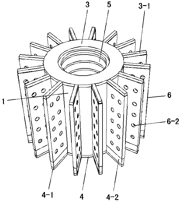
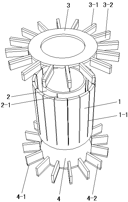
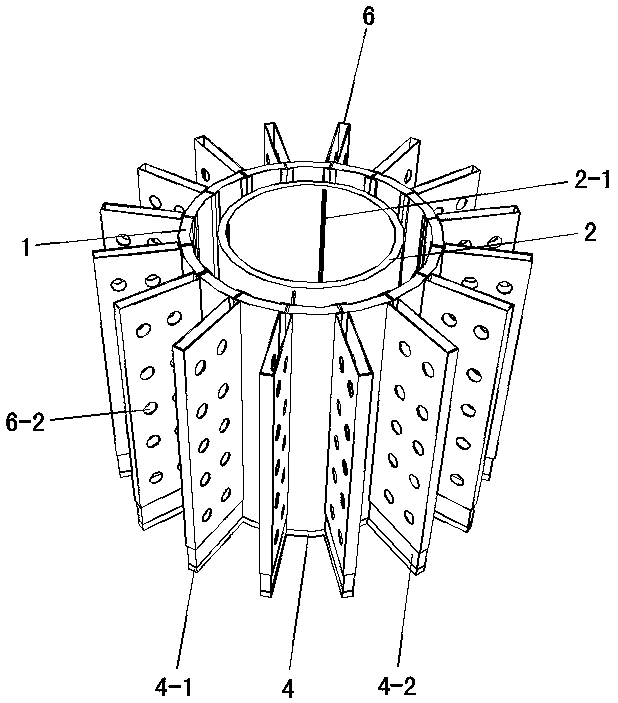
[0015] Specific implementation mode one: as Figure 1~Figure 5 As shown, the present invention discloses a new type of LED lamp heat dissipation structure, which includes a main body installation shell, a lamp holder 5, a plurality of heat dissipation fins 6 and a plurality of high thermal conductivity rectangular metal sheets 7, and the main body installation shell includes a coaxial interval The outer cylinder 1 and the inner cylinder 2 are sleeved, and the upper and lower ends of the outer cylinder 1 and the inner cylinder 2 are respectively bonded and fixed by the upper sealing ring 3 and the lower sealing plate 4, and the outer cylinder 1 Mercury is injected between the cylinder and the inner cylinder 2, and the liquid level of the mercury is lower than the upper surface of the outer cylinder 1 and the inner cylinder 2, and the upper end of the outer cylinder 1 wall is evenly provided with a plurality of vertical gaps along the circumferential direction One 1-1, each of t...

specific Embodiment approach 2

[0016] Specific implementation mode two: as figure 1 , 2 As shown, this embodiment is a further description of specific embodiment 1. The outer peripheral surface of the upper sealing ring 3 is uniformly fixed with a plurality of connecting rods-3-1 along the circumferential direction, and the plurality of connecting rods- 3-1 are arranged radially along the upper sealing ring 3 and are arranged in correspondence with a plurality of cooling fins 6 one by one. A positioning block 3-2 is fixed below each connecting rod 3-1, and each of the positioning blocks A 3-2 matching is inserted in the upper end of the corresponding cooling fin 6, the lower sealing plate 4 is a circular plate matching the lower end of the outer cylinder 1, and the circumferential surface of the lower sealing plate 4 is evenly fixed along the circumferential direction. Two connecting rods 4-1, the multiple connecting rods 4-1 are arranged radially along the lower sealing plate 4 and arranged in one-to-one ...

specific Embodiment approach 3

[0017] Specific implementation mode three: as Figure 4 As shown, this embodiment is a further description of Embodiment 1 or Embodiment 2, and each of the heat dissipation fins 6 is provided with a plurality of heat dissipation holes 6-2.


PUM


Abstract

The invention provides a novel LED lamp heat dissipation structure and relates to the heat dissipation structure. An outer barrel and an inner barrel are pasted and fixed through an upper sealing ringand a lower sealing plate, and hydrargyrum is injected into the portion between the outer barrel and the inner barrel. The upper end of the barrel wall of the outer barrel is provided with a plurality of first vertical gaps. Heat dissipation fins are formed in the manner that two opposite ends of every two metal sheets are folded and extruded into a rectangular barrel shape, the two opposite endsof each heat dissipation fin are outwards turned and bent into a T-shaped inserting portion, the multiple heat dissipation fins are inserted into the corresponding first vertical gaps through the T-shaped inserting portions correspondingly, and the first vertical gaps are sealed through a sealant. A lampholder is pasted and fixed inside the inner barrel, the middle of the barrel wall of the innerbarrel is provided with a plurality of second vertical gaps, the middles of a plurality of high-heat-conductive rectangular metal sheets are inserted into the corresponding second vertical gaps correspondingly, the second vertical gaps are sealed through a sealant, the outer end of each high-heat-conductive rectangular metal sheet stretches into the portion between the outer barrel and the innerbarrel, and the inner end of each high-heat-conductive rectangular metal sheet is tightly attached to the lampholder. Heat conduction and transition are performed through the hydrargyrum, and the dissipation is stable and efficient.

Description

technical field [0001] The invention relates to a heat dissipation structure, in particular to a novel LED lamp heat dissipation structure. Background technique [0002] In the field of lighting, LED lamps have basically replaced traditional tungsten lamps due to their advantages of energy saving, environmental protection and relatively long service life compared with traditional tungsten lamps. [0003] As we all know, LED lights will generate a lot of heat when they are used, especially high-power LED lights. If the heat generated cannot be discharged in time, it will affect the lighting effect of the LED lights and even shorten the service life. Therefore, the heat dissipation of LED lights Structure plays a particularly important role. [0004] At present, there are generally two types of heat dissipation structures for LED lamps. One is an integrated heat dissipation structure directly die-cast. This heat dissipation structure has thicker heat dissipation fins and weak...

Claims


Application Information

Patent Timeline
Patent Type & Authority Applications(China)
IPC IPC(8): F21V29/77F21V29/83F21V29/87F21V29/89F21V31/00F21V19/00F21Y115/10
CPCF21V29/77F21V19/005F21V29/83F21V29/87F21V29/89F21V31/005F21Y2115/10
Inventor 付春明熊大曦廖新胜
Owner 江苏泓睿德智能科技有限公司
Why Eureka
Try Eureka