Position Error Compensation Method for Coreless Current Sensor

A current sensor and error compensation technology, which is applied in the field of position error compensation method, can solve problems such as troublesome industrial applications, complex and variable positional relationship between current-carrying wires and sensors, and achieve the effect of improving measurement accuracy

Inactive Publication Date: 2019-11-12
FUZHOU UNIV
View PDF6 Cites 0 Cited by
  • Summary
  • Abstract
  • Description
  • Claims
  • Application Information

AI Technical Summary

Problems solved by technology

These constraints create problems for industrial applications, especially in power measurement
[0005] In practical applications, the positional relationship between the current-carrying wire and the sensor is complex and variable

Method used


Image

  • Position Error Compensation Method for Coreless Current Sensor
  • Position Error Compensation Method for Coreless Current Sensor
  • Position Error Compensation Method for Coreless Current Sensor

Examples


Embodiment Construction

[0020] The present invention will be further explained below in conjunction with the accompanying drawings and specific embodiments.

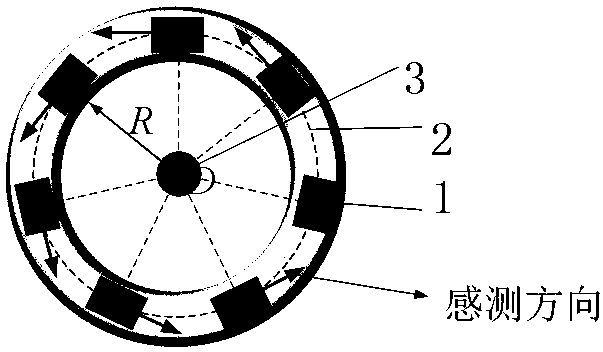
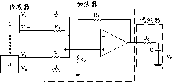
[0021] A position error compensation method for a coreless current sensor of the present invention arranges a plurality of magnetic field sensors without a magnetic core evenly on a circular printed circuit board (similar to an ampere ring), and by proportionalizing the magnetic field values ​​sensed by each sensor Weighting reduces the measurement error caused by the positional relationship, and changes the proportional relationship between the inner diameter of the ring in the sensor array and the diameter of the current-carrying conductor in the design, so that the designed sensor can meet the accuracy requirements. Specifically include the following steps: including the following steps: Step S1: uniformly install n magnetic field sensors without magnetic cores on a circular printed circuit board, the sensing direction of the n magnetic field...


PUM


Abstract

The invention provides a position error compensation method of a magnetic-core-free current sensor. The position error compensation method of the magnetic-core-free current sensor comprises the following steps: uniformly mounting n magnetic field sensors without magnetic cores on a circular printing circuit board, wherein the sensing directions of the n magnetic field sensors are the same as an ampere circuital direction; outputs of the n magnetic field sensors are separately connected with an input of an adding device; the adding device superposes and summarizes output voltages of the sensors, and an output of the adding device is connected with a filter; and after the number n of the magnetic field sensors is determined, the proportional relation between the circular inner diameter of the circular printing circuit board and the diameter of a carrier conductor is designed through a solver, therefore, the movement range of a current-carrying conductor is limited, and requirements for measurement errors are met.

Description

technical field [0001] The invention specifically relates to a position error compensation method of a coreless current sensor. Background technique [0002] In industrial applications, the non-contact detection method has become the solution for most current measurements because of the simple process and low cost of the system. These schemes mainly rely on different magnetic field sensing technologies, such as Hall effect, magnetoresistive effect, Faraday effect, etc. [0003] Among the existing current sensors, most of them are designed by adding a magnetic core to increase the magnetic flux density, thereby improving the sensitivity. The addition of the magnetic core limits the measurement frequency band of the current sensor. In recent years, some coreless high-sensitivity linear magnetic field sensors have been developed and used for current measurement. These non-contact measurement methods based on coreless current sensors have attracted high interest in the field ...

Claims


Application Information

Patent Timeline
Patent Type & Authority Patents(China)
IPC IPC(8): G01R35/00
CPCG01R35/005
Inventor 陈坤隆项宇锴陈夏南林栩
Owner FUZHOU UNIV
Why Eureka
Try Eureka