
ACE type mount antenna

A mount and antenna technology, which is applied in the connection of antenna grounding switch structure, antenna support/installation device, etc., can solve the problems of small-diameter antenna wiring difficulties, complex ship-borne antenna system, and complicated cable layout, etc., to reduce manpower The effects of time cost, antenna cost saving, and wiring efficiency improvement

Pending Publication Date: 2018-09-28
NO 54 INST OF CHINA ELECTRONICS SCI & TECH GRP
View PDF0 Cites 0 Cited by
  • Summary
  • Abstract
  • Description
  • Claims
  • Application Information

AI Technical Summary

Problems solved by technology

[0003] However, due to the complexity of the shipboard antenna system and the large number of modules, the layout of the cables between the modules is complicated, especially there is no mature and reliable solution for the layout of the C-axis and E-axis cables, and the cable layout depends entirely on human trial and error. , the influence of human factors is greater, especially it is more difficult to route on small-diameter antennas

Method used


Image

  • ACE type mount antenna
  • ACE type mount antenna
  • ACE type mount antenna

Examples


Embodiment Construction

[0021] In order to make it easier for those skilled in the art to understand the technical solution of this patent, and at the same time, in order to make the technical purpose, technical solution and beneficial effect of this patent clearer, and to fully support the protection scope of the claims, the following is a specific case in the form of this patent. The technical solution of the patent makes further and more detailed descriptions.

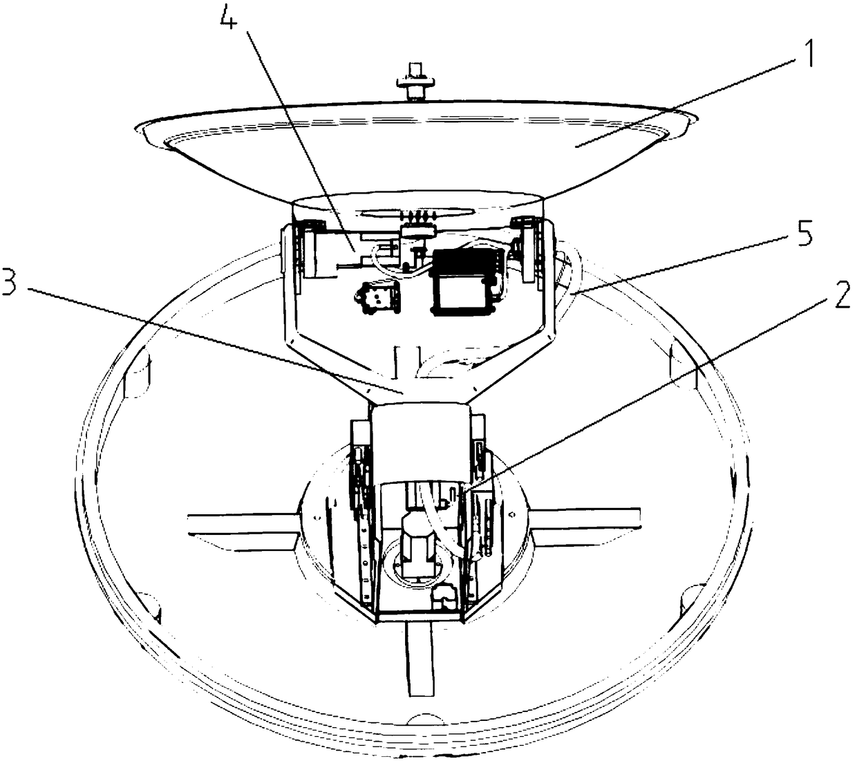
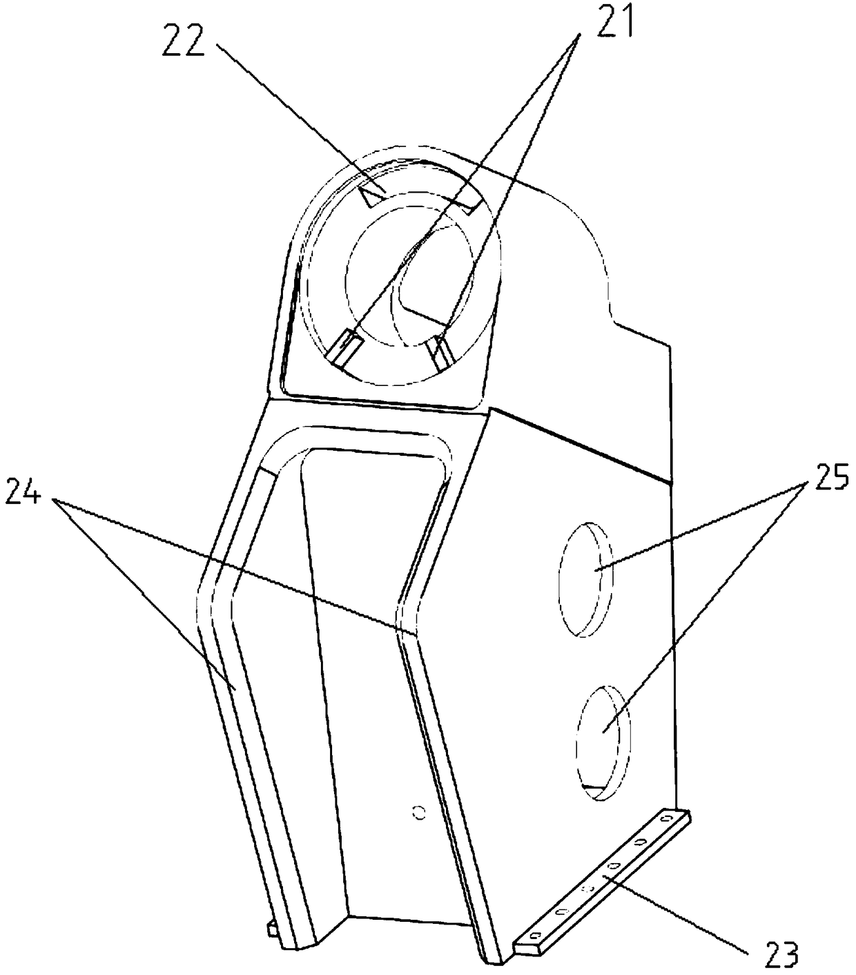
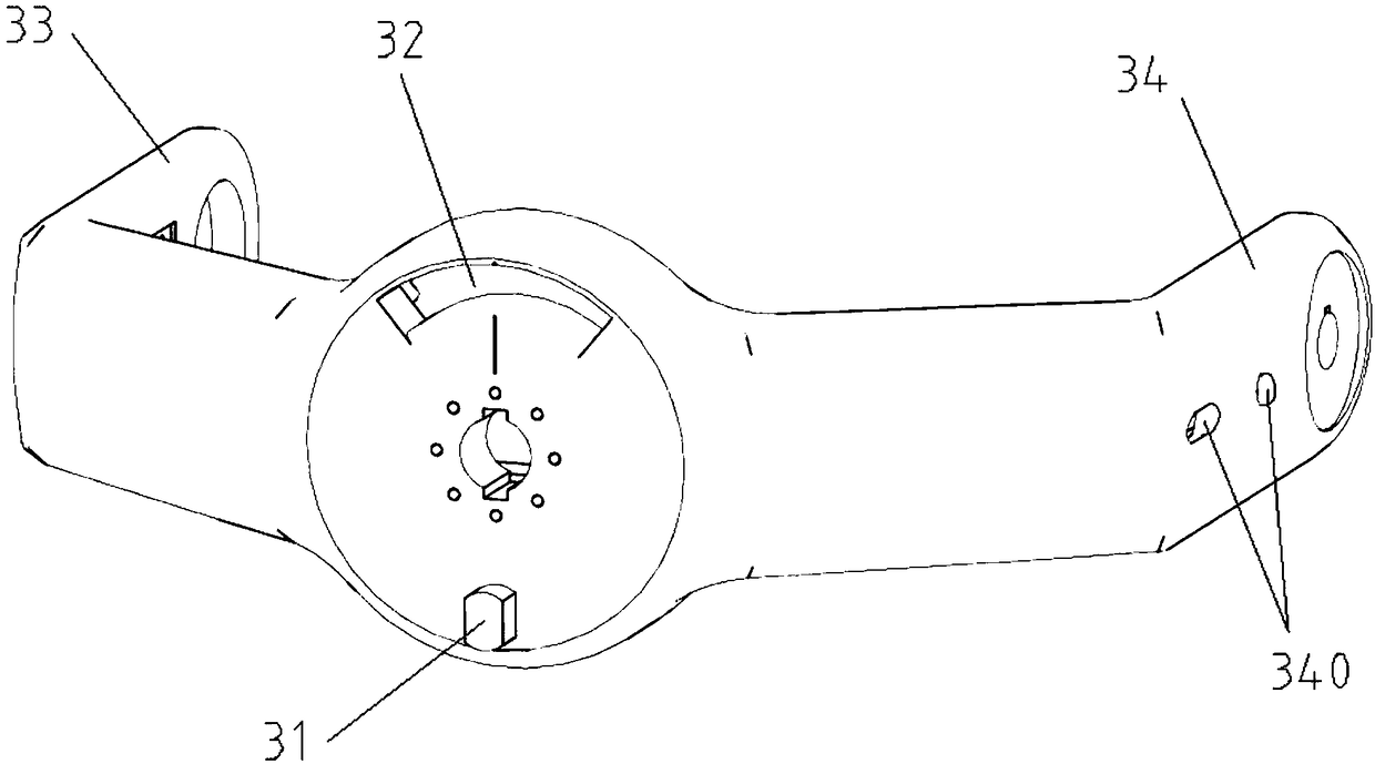
[0022] Such as Figure 1~4 As shown, an ACE type pedestal antenna includes an antenna surface 1, a cross column 2, a cross axis 3, a control box (not shown), a plurality of cables 5 extending from the control box, and a The low noise amplifier and power amplifier (not marked) on the side; the cross shaft 3 is connected to the bearing of the cross column 2 through the shaft hole (not marked) provided on the cross column 2, and the front end of the cross shaft 3 protrudes Two pitching arms 33, 34, the antenna surface 1 is connected to the t...


PUM


Abstract

The invention discloses an ACE type mount antenna, and belongs to the technical field of the antenna. The mount antenna comprises an antenna face, a cross upright, a cross shaft, a control box, a cable and an amplifier; the cross shaft is connected with the cross upright through a shaft hole, two pitching support arms extend out from the front end of the cross shaft, the antenna face is respectively connected with two pitching support arms through two pitching shafts; one of the two pitching shafts is connected with a pitching driving motor, the other one is a hollow shaft, and a threading hole is formed in the pitching support arm at one side of the hollow shaft; the control box is arranged in front of the cross upright, an arc cabling slot hole concentric to the shaft hole is arranged onthe cross upright, and a cabling hole is formed in the cross shaft; the cable is respectively connected with the pitching driving motor and the amplifier after orderly penetrating the cabling slot hole, the cabling hole, the first threading hole and the hollow shaft. The wiring structure disclosed by the invention is convenient for fast wiring, the wiring efficiency is improved, the twining of the cable is prevented, and the wiring reliability is increased.

Description

technical field [0001] The invention relates to the technical field of antennas, in particular to an ACE type pedestal antenna. Background technique [0002] With the development of satellite communication technology, more and more shipboard communication antennas are used, but the space of the ship is limited, so antennas with small apertures are more popular on the basis of meeting the requirements; The advantages of compact structure and light weight are widely used. The meanings of A, C, and E in the ACE type mount antenna are: A is the initial letter of Azimuth, indicating the azimuth axis; C is the initial letter of Cross, indicating the cross axis; E is the initial letter of Elevation, indicating the pitch axis. [0003] However, due to the complexity of the shipboard antenna system and the large number of modules, the layout of the cables between the modules is complicated, especially there is no mature and reliable solution for the layout of the C-axis and E-axis...

Claims


Application Information

Patent Timeline
IPC IPC(8): H01Q1/12H01Q1/50
CPCH01Q1/12H01Q1/50
Inventor 杨亚军闫少雄米宏伟王京城刘昕张立军李洪强程东起郭云玲王小宇宫玉松孙孟林苏广平赵航秦茜
Owner NO 54 INST OF CHINA ELECTRONICS SCI & TECH GRP
Learn More