Cable conveyor

A technology of cable conveyors and bottom boxes, which is applied in the direction of cable laying equipment, etc., can solve problems such as poor working stability, small clamping force, and easy slipping, and achieve the effects of ensuring construction progress and quality, improving service life, and reducing production costs

Inactive Publication Date: 2018-09-28
江苏伊居科技有限公司
View PDF0 Cites 5 Cited by
  • Summary
  • Abstract
  • Description
  • Claims
  • Application Information

AI Technical Summary

Problems solved by technology

[0002] The cable conveyor is an electric machine for laying power cables (or communication cables). It can be used in conjunction with cable tractors, hoists and other cable laying machines. It is convenient and fast in construction, and can greatly save manpower and material resources. Reduce construction costs. With the continuous development and improvement of social living standards, the scale of urban power grids is also expanding. The traditional way of laying cables manually can no longer meet the requirements. In order to reduce the labor intensity of laying cables and ensure construction quality, the current domestic A variety of cable conveyors for pulling and transporting cables have been developed, but the existing cable conveyors have the disadvantages of small thrust, small contact surface of the clamped and conveyed cables, small clamping force, easy slipping, and poor working stability. Most of the cable conveyors above use manual clamping to clamp the cables. Since the clamping devices are mostly inside the conveyor, the clamping of the cables is mostly based on the feeling of the staff, so it is very easy to cause damage to the cables. The clamping is not reliable, and it is very easy to slip, causing work interruption and seriously affecting the construction quality and construction progress

Method used


Image

  • Cable conveyor
  • Cable conveyor
  • Cable conveyor

Examples


Embodiment Construction

[0014] The following will clearly and completely describe the technical solutions in the embodiments of the present invention with reference to the accompanying drawings in the embodiments of the present invention. Obviously, the described embodiments are only some of the embodiments of the present invention, not all of them. Based on the embodiments of the present invention, all other embodiments obtained by persons of ordinary skill in the art without making creative efforts belong to the protection scope of the present invention.

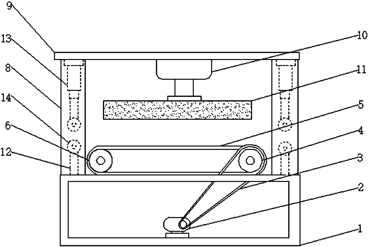
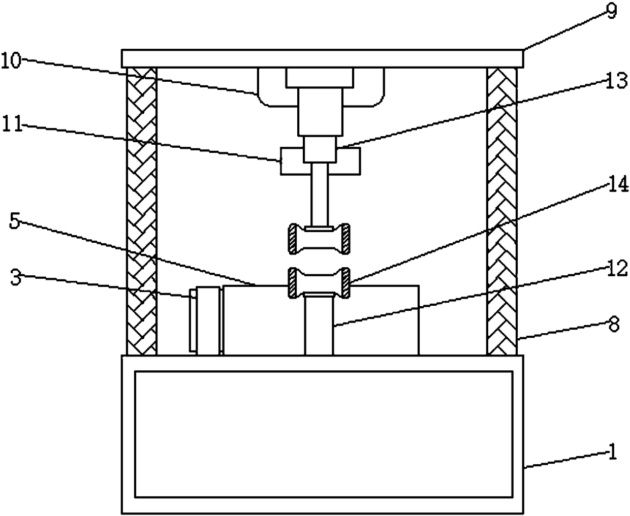
[0015] see Figure 1-4 , the present invention provides a technical solution: a cable conveyor, including a bottom box 1, a motor 2 is fixedly connected to the bottom of the inner wall of the bottom box 1, the rotating shaft of the motor 2 is connected to a pulley 4 through a belt 3, and the pulley 4 passes through an endless track 5. The transmission is connected with crawler discs 6. Both sides of the top of the bottom box 1 are fixedly connect...


PUM


Abstract

The invention discloses a cable conveyor comprising a bottom box, wherein the bottom of an inner wall of the bottom box is fixedly connected with a motor, a rotating shaft of the motor is in transmission connection with a belt pulley through a belt, the belt pulley is in transmission connection with a crawler disk through an annular crawler, supporting columns are fixedly connected to both sides of the top of the bottom box, one end of each supporting column away from the bottom box is fixedly connected with a top plate, the bottom of the top plate is fixedly connected with a cylinder, and a clamping block is fixedly connected with one side of the cylinder away from the top plate through a piston. The cable conveyor adopts double-layer clamping to eradicate the problem that a clamped cabledeviates from or is extruded out from a clamping area in the prior art, thus ensuring the construction progress and quality, further improving the working efficiency, reducing the production cost andprolonging the service life of the machine, no abrasion damage is generated to the cable, and the cable conveyor has the advantages of being convenient to use, stable in operation and low in failurerate.

Description

technical field [0001] The invention relates to the technical field of cables, in particular to a cable conveyor. Background technique [0002] The cable conveyor is an electric machine for laying power cables (or communication cables). It can be used in conjunction with cable tractors, hoists and other cable laying machines. It is convenient and fast in construction, and can greatly save manpower and material resources. Reduce construction costs. With the continuous development and improvement of social living standards, the scale of urban power grids is also expanding. The traditional way of laying cables manually can no longer meet the requirements. In order to reduce the labor intensity of laying cables and ensure construction quality, the current domestic A variety of cable conveyors for pulling and transporting cables have been developed, but the existing cable conveyors have the disadvantages of small thrust, small contact surface of the clamped and conveyed cables, s...

Claims


Application Information

Patent Timeline
Patent Type & Authority Applications(China)
IPC IPC(8): H02G1/06
CPCH02G1/06
Inventor 田清
Owner 江苏伊居科技有限公司
Why Eureka
Try Eureka