Disk-type double-support double-stator permanent magnetic synchronous traction machine

A synchronous traction machine, double support technology, applied in the direction of electromechanical devices, control mechanical energy, magnetic circuit static parts, etc., can solve the problems of increasing the volume of the traction machine, the bending deformation of the shaft, the overall structure is not too compact, etc. Effects of Power Density and Traction Capacity

Pending Publication Date: 2018-09-28
SHANGHAI GIE EM
View PDF0 Cites 3 Cited by
  • Summary
  • Abstract
  • Description
  • Claims
  • Application Information

AI Technical Summary

Problems solved by technology

The traditional thin permanent magnet synchronous traction machine is usually a cantilevered outer rotor structure. The shaft of the cantilever structure is subject to a large bending moment, which is easy to cause the shaft to bend and deform, and the service life of the bearing is short
In order to improve the traction capacity of the traction machine, the usual practice is to design the shaft very thick and select larger bearings, or to install the bearings at both ends of the rotor assembly on the machine base and bracket on both sides respectively. The method usually increases the volume of the traction machine, and the overall structure is not too compact. Therefore, it is necessary to optimize the structure of the traction machine to make the traction machine small in size, high in power density, and strong in traction capacity.

Method used


Image

  • Disk-type double-support double-stator permanent magnetic synchronous traction machine
  • Disk-type double-support double-stator permanent magnetic synchronous traction machine
  • Disk-type double-support double-stator permanent magnetic synchronous traction machine

Examples


Embodiment Construction

[0035] In order to make the technical means, creative features, goals and effects achieved by the present invention easy to understand, the present invention will be further described below in conjunction with specific illustrations.

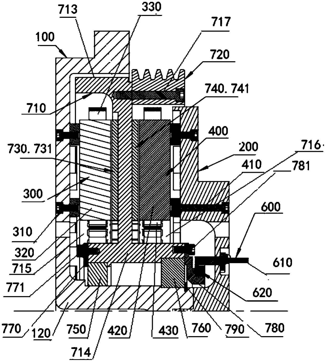
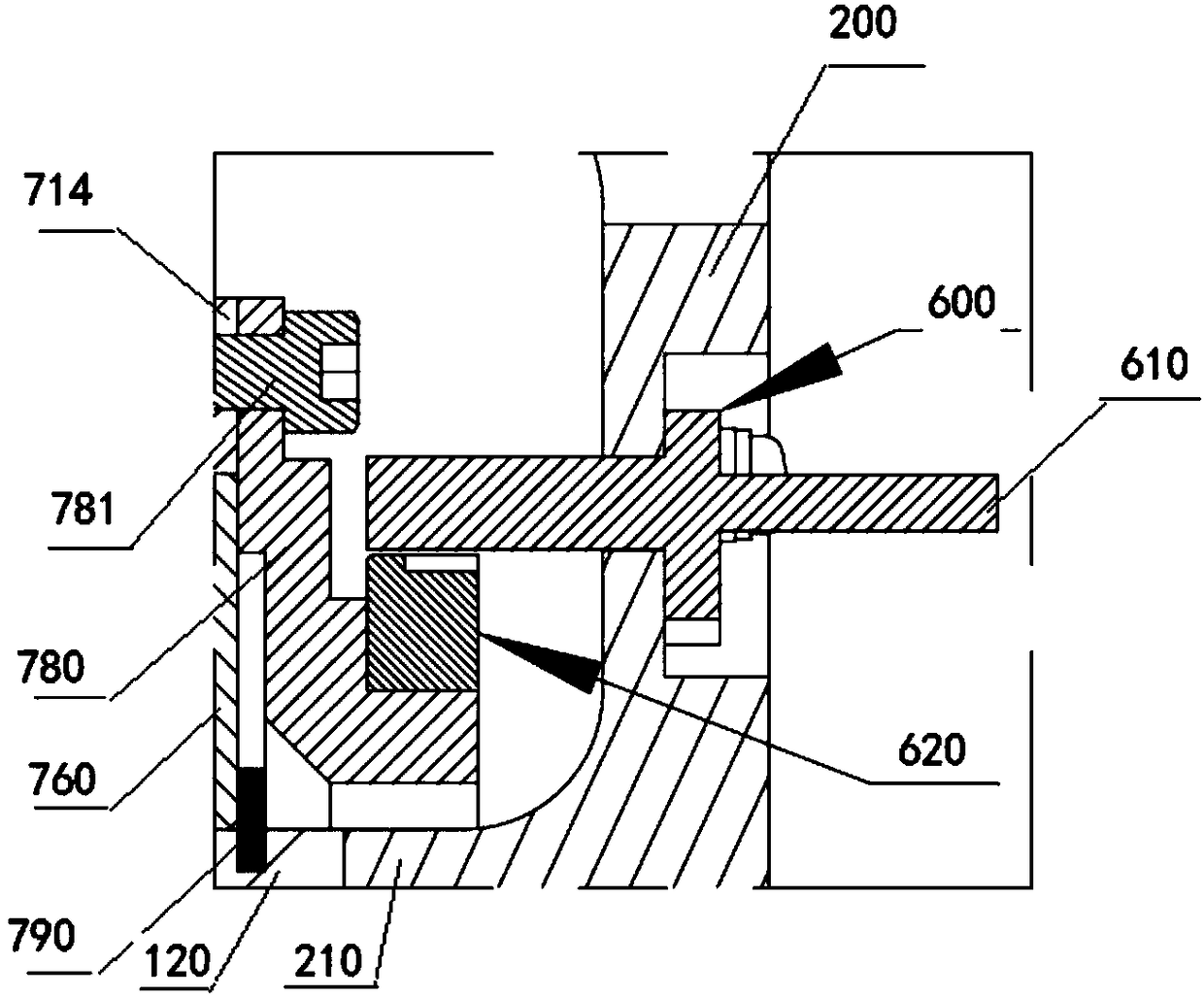
[0036] see Figure 1 to Figure 16 , the disc-type double-support double-stator permanent magnet synchronous traction machine shown in the figure consists of a first housing 100, a second housing 200, a first stator assembly 300, a second stator assembly 400, a rotor assembly, and a brake 500 , Encoder 600 and so on.

[0037] A first axially protruding central mounting portion 120 and a first axially protruding peripheral mounting portion 130 are disposed on the first housing 100 .

[0038] A second axially protruding central mounting portion 210 and a second axially protruding peripheral mounting portion 220 are disposed on the second housing 200 .

[0039] In this embodiment, the first stator assembly 300 is fixedly installed on the correspon...


PUM


Abstract

The invention discloses a disk-type double-support double-stator permanent magnetic synchronous traction machine which comprises a first shell, a second shell, a first stator assembly, a second statorassembly, a rotor assembly, an encoder, a brake and the like, wherein the rotor assembly comprises a first permanent magnet group and a second permanent magnet group; permanent magnets of the first permanent magnet group and permanent magnets of the second permanent magnet group are all arranged in a ring shape at both left and right sides of a brake drum; the first stator assembly and the firstpermanent magnet group interact with each other to generate a torque; the second stator assembly and the second permanent magnet group interact with each other to generate a torque; the first stator assembly and the second stator assembly can be simultaneously powered on for loading, and can also be separately powered on for loading; and each stator assembly can drive the rotor assembly to rotate.Compared to a traction machine with a conventional structure, the disk-type double-support double-stator permanent magnetic synchronous traction machine disclosed by the invention is more stable andcompact in integral structure; a power density and traction loading capacity of the traction machine are improved; and the difficult problem of design of a thin heavy-load traction machine is solved.

Description

technical field [0001] The invention relates to the technical field of permanent-magnet synchronous traction machines, in particular to a disc-type double-support double-stator permanent-magnet synchronous traction machine. Background technique [0002] With the rapid development of science and technology and society, the use and demand of elevators are increasing, so the application of permanent magnet synchronous traction machines is becoming more and more extensive. In general, in order to reduce construction costs, the space in the machine room will not It is very sufficient, and in order to save installation space, thin permanent magnet synchronous traction machines are used more and more. The traditional thin permanent magnet synchronous traction machine usually has a cantilevered outer rotor structure. The shaft of the cantilever structure is subjected to a large bending moment, which easily leads to bending deformation of the shaft and short service life of the beari...

Claims


Application Information

Patent Timeline
Patent Type & Authority Applications(China)
IPC IPC(8): H02K16/04B66B11/04H02K7/102H02K1/16
CPCH02K16/04B66B11/043H02K1/16H02K7/102
Inventor 张汉允
Owner SHANGHAI GIE EM
Why Eureka
Try Eureka