Remote sensing to derive calibrated power measurements

A power measurement and power technology, applied in the direction of measuring electric power, electric power measurement by current/voltage, electric power measurement by applying digital technology, etc. unrealistic issues

Inactive Publication Date: 2018-09-28
EARTH NETWORKS
View PDF2 Cites 2 Cited by
  • Summary
  • Abstract
  • Description
  • Claims
  • Application Information

AI Technical Summary

Problems solved by technology

[0005] However, installation of CT clamps is difficult and dangerous as this step requires the removal of the outer protective panel of the electrical breaker box and further requires the installer to be in close contact with high power electrical wires which can result in personal injury or even death
This type of installation is not practical for homeowners to complete; rather than perform the installation comfortably, most homeowners choose to hire an electrical contractor to perform the work at a significant expense
Additionally, CT clamp installation takes a significant amount of time due to the labor involved in removing the fuse box cover, carefully connecting the CT clamp and associated wires
Even a professional electrician can take thirty minutes or more to install

Method used


Image

  • Remote sensing to derive calibrated power measurements
  • Remote sensing to derive calibrated power measurements
  • Remote sensing to derive calibrated power measurements

Examples


Embodiment Construction

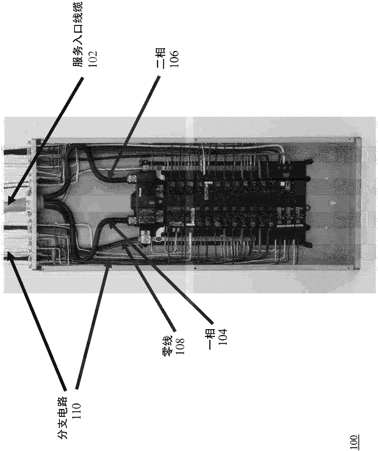
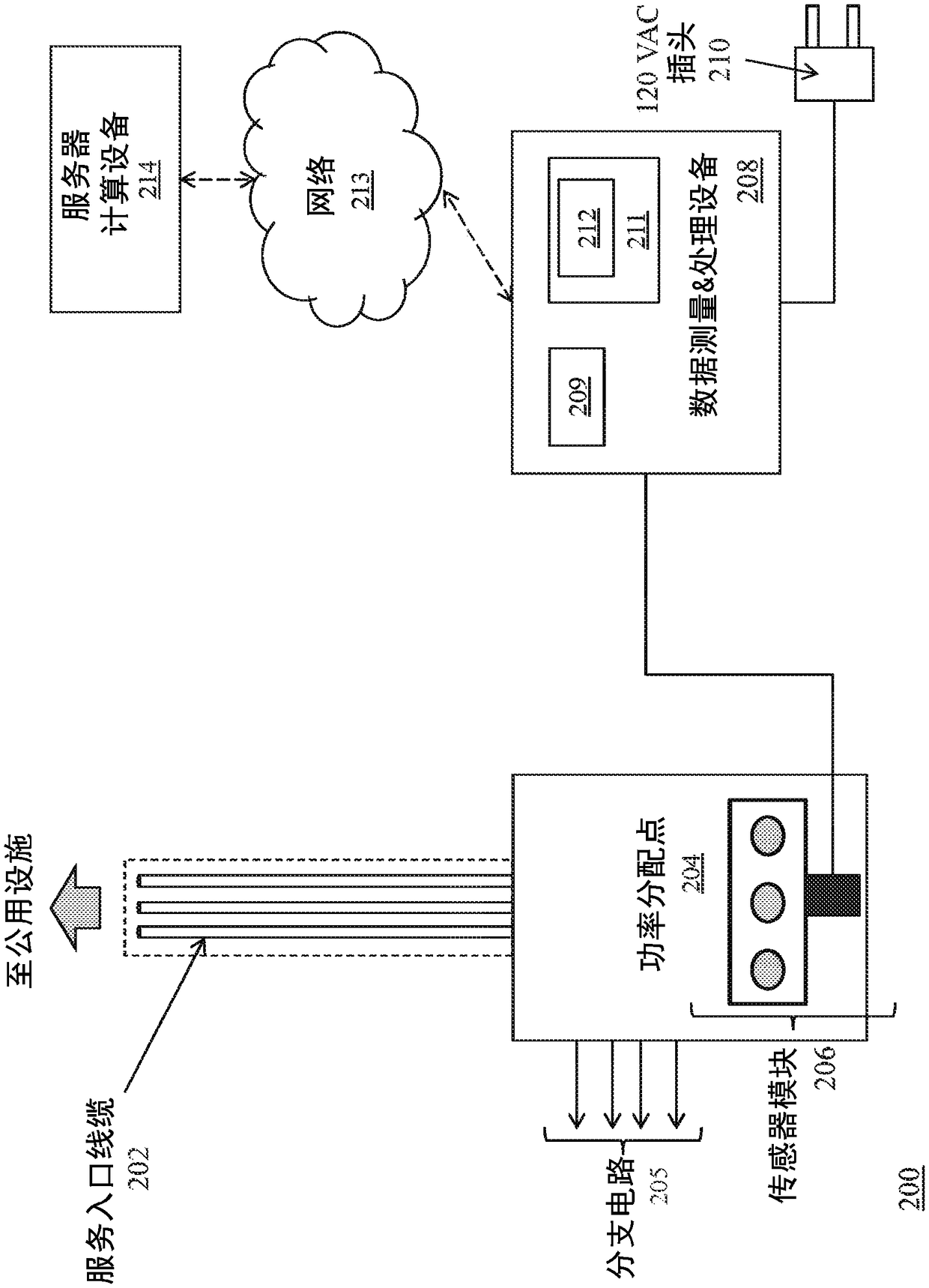
[0041] figure 2 is a block diagram of a system 200 for remote sensing to derive calibrated power measurements of power distribution points. The system 200 includes a service entry cable 202 that enters a power distribution point 204 (e.g., an electrical breaker box) that transmits power received from the service entry cable to a branch circuit 205 that feeds power to appliances and outlets, such as People will find it in residential environments or other buildings or facilities.

[0042] System 200 also includes a sensor module 206 located near power distribution point 204 . exist figure 2 In the example shown in , the sensor module 206 is secured to the exterior of the power distribution point 204 . However, as noted above, it should be understood that sensor modules in some embodiments are positioned in various locations near the power distribution point 204 , such as on or near the service entrance cable 202 , or on a wall near the power distribution point 204 .

[00...


PUM


Abstract

Described herein are methods and systems for remote sensing to derive a calibrated power measurement for a power distribution point. Magnetic field sensors of a sensor module sense a magnetic field emitted by the power distribution point. A first processor generates an uncalibrated power measurement for each magnetic field sensor, the uncalibrated power measurement derived from the magnetic fieldsensed by the magnetic field sensor and a voltage carried by the power distribution point. A second processor determines a response of each magnetic field sensor to a known power load being drawn through the power distribution point. The second processor derives a transfer function using the response of each magnetic field sensor to the known power load. The second processor applies the transfer function to the uncalibrated power measurement for each magnetic field sensor to generate the calibrated power measurement for the power distribution point.

Description

[0001] related application [0002] This application claims the benefit of priority to US Provisional Patent Application No. 62 / 232,278, filed September 24, 2015, which is hereby incorporated by reference in its entirety. technical field [0003] The subject matter of this application generally relates to remote sensing to derive calibrated power measurements. Background technique [0004] Measuring electrical loads and fluctuations in residential and commercial environments is currently accomplished through current transformer (CT) clamp technology. Products such as smart meters and other power monitoring products such as the TED5000 series available from Energy Corp. of Charleston, South Carolina, Neural Sensors available from Neurotechnology Inc. of Vancouver, British Columbia, Canada, and EyedroGreen, available from Kitchener, Ontario, Canada The EHEM1 Home Power Monitor, obtained by Solutions, Inc., uses CT technology because discerning power usage is relatively straig...

Claims


Application Information

Patent Timeline
Patent Type & Authority Applications(China)
IPC IPC(8): G01R15/00G01R15/14G01R19/00G01R21/00G01R21/06G01R33/00
CPCG01R21/133G01R22/10G01R35/04G01R15/207G01R35/005G01R22/061G01R22/065
Inventor R·S·马歇尔S·赫克曼C·刘C·D·斯卢普D·比克斯勒S·斯蒂克斯E·斯蒂克斯
Owner EARTH NETWORKS
Why Eureka
Try Eureka