
A display method and handheld electronic device

A display method and display technology, applied to static indicators, cathode ray tube indicators, instruments, etc., can solve problems such as user experience degradation, nonlinear distortion, color distortion, etc., achieve clear images and guarantee display effects

Active Publication Date: 2022-02-01
HUAWEI TECH CO LTD
View PDF8 Cites 0 Cited by
  • Summary
  • Abstract
  • Description
  • Claims
  • Application Information

AI Technical Summary

Problems solved by technology

[0003] The defect shown in the prior art is that, due to the radian chamfering at the edge of the transparent panel, the light passing through it is refracted, and the image normally displayed at the edge of the transparent panel will appear nonlinear distortion and color distortion, such Visual effects degrade user experience

Method used


Image

  • A display method and handheld electronic device
  • A display method and handheld electronic device
  • A display method and handheld electronic device

Examples


Embodiment 1

[0180] Embodiment 1: The display method provided by the embodiment of the present invention can prevent non-linear distortion of the image at the edge of the transparent panel of the electronic device.

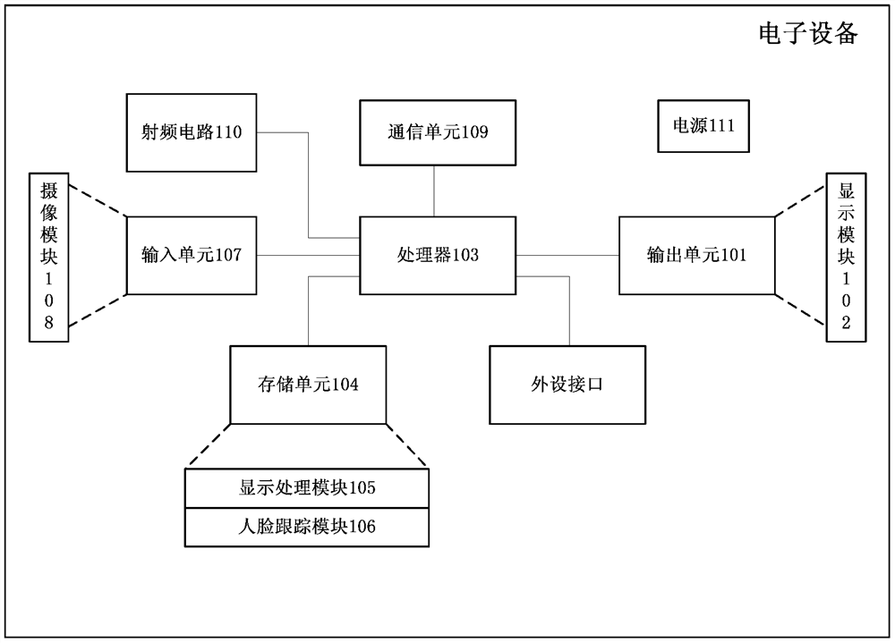
[0181] combine first figure 1 The specific structure of the electronic device to which the display method shown in the embodiment of the present invention can be applied is described in detail.

[0182] in, figure 1 Shown is a specific structural schematic diagram of an electronic device according to a specific embodiment of the present invention.

[0183] The electronic equipment includes such as figure 1 Components are shown that communicate over one or more buses.

[0184] Those skilled in the art can understand that, figure 1 The structure of the electronic equipment shown in does not constitute a limitation to the present invention. It can be a bus structure or a star structure, and can also include more or less components than shown in the illustration, or combine so...


PUM


Abstract

A display method and a handheld electronic device, the display method comprising acquiring an optical deformation parameter (401) of a first area of ​​a display, and performing shape transformation on first image data according to the optical deformation parameter of the first area to obtain second image data (402), the first image data is image data to be displayed in the first area, and the second image data is displayed in the first area (403). By adopting the display method, the image displayed at the edge of the transparent panel will not be deformed, which ensures the clarity of the image displayed on the transparent panel, improves the user's visual experience in the process of using the electronic device, and improves the appearance of the electronic device. .

Description

technical field [0001] The invention relates to the field of electronic equipment, in particular to a display method and a handheld electronic equipment. Background technique [0002] As the display of the electronic device becomes larger and larger, the frame of the display of the electronic device becomes narrower and narrower for the sake of aesthetic appearance. The prior art discloses an electronic device, in which a display with a planar structure is covered with a transparent panel, and the edge of the transparent panel is outside the edge of the display. The edge of the transparent panel is curved, and the width of the curved edge of the transparent panel is about 1-2mm. The edge of the transparent panel is made into a curved transition shape, and then the refraction of light on the surface of different media The principle is to make the light emitted from the edge of the display look like light emitted from the edge of the transparent panel, so that the user cannot...

Claims


Application Information

Patent Timeline
IPC IPC(8): G06T3/40
CPCG06T3/40G02F1/133308G02F1/13338G02F1/133615G09G5/10G09G2320/062G09G2320/068G02F1/13332G02F1/133607G02F1/133601
Inventor 秦超朱家庆郜文美余晓艳
Owner HUAWEI TECH CO LTD
Learn More