Automatic boxing mechanism for electronic packaging materials
An electronic packaging material, automatic packing technology, applied in the directions of packaging, transportation and packaging, single objects, etc., can solve the problem of time-consuming and laborious manual packing, impurities mixed into the packing box, and endangering the health of workers. , Eliminate the influence of human factors, and ensure the effect of workers' health
- Summary
- Abstract
- Description
- Claims
- Application Information
AI Technical Summary
Problems solved by technology
Method used
Image

Examples
Embodiment Construction
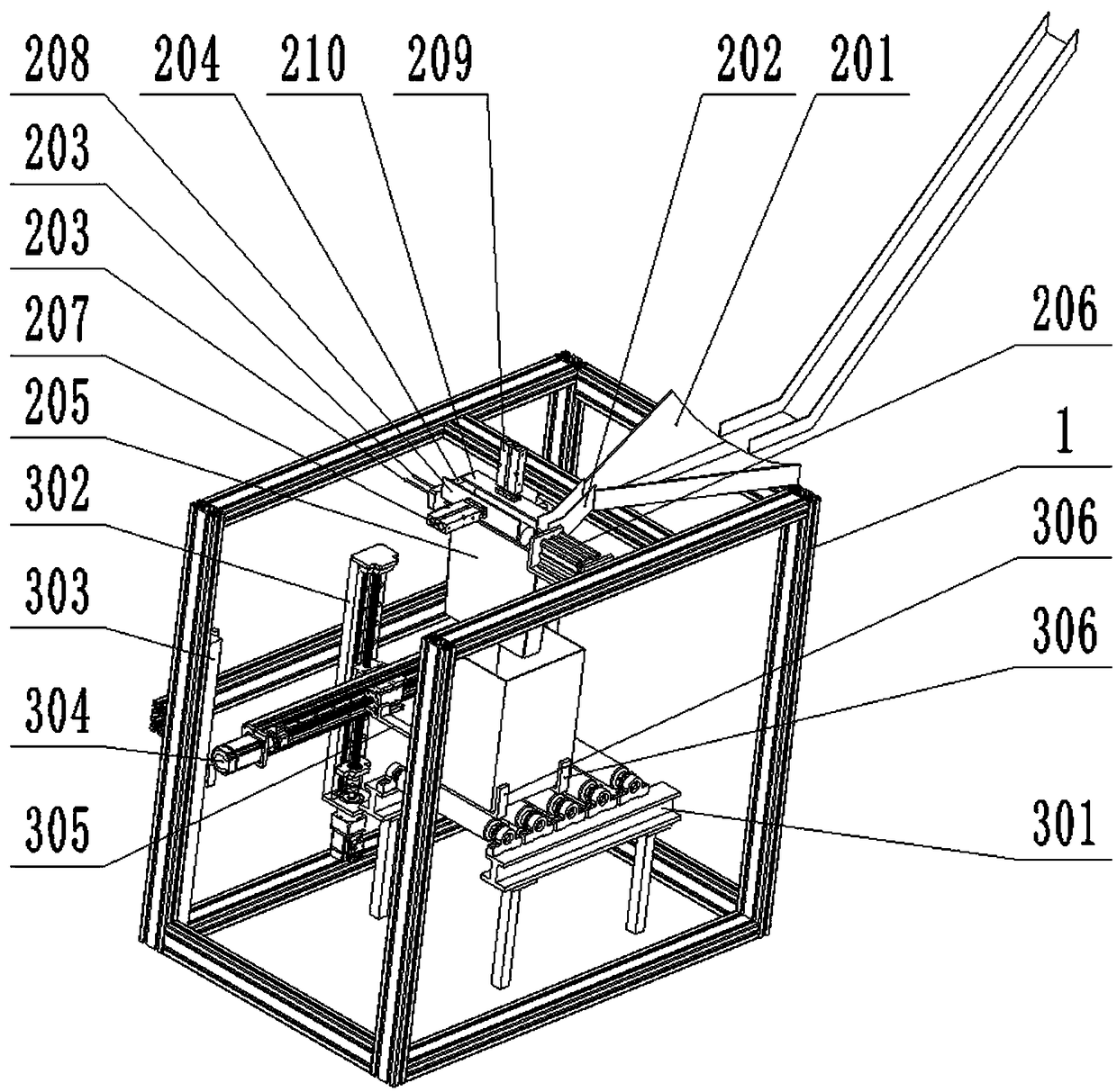
[0018] An automatic packing mechanism for electronic packaging materials, including a box-shaped frame 1, a feeding sub-mechanism, and a combined driving sub-mechanism;
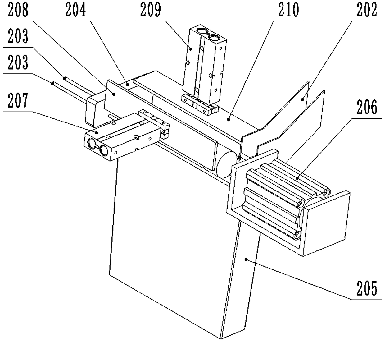
[0019] The material feeding sub-mechanism comprises a gathering tank 201, a material guide tank 202, a material supporting beam 203, a material blocking plate 204, a feeding square tube 205, a first cylinder 206, a second cylinder 207, a pushing plate 208, a third cylinder 209, pressing plate 210;
[0020] The aggregate trough 201 is fixed longitudinally on the box-shaped frame 1, and the notch of the aggregate trough 201 faces upwards; the groove width of the aggregate trough 201 gradually becomes smaller from front to back, and the inner surface of the aggregate trough 201 is left and right high. , a low arc surface in the middle; the material guide trough 202 is obliquely fixed on the box-shaped frame 1 with the front high and the rear low, and the notch of the material guide trough 202 faces upward; The ...
PUM
 Abstract
Description
Claims
Application Information