Pulley block type electric vehicle door lock structure

A technology of electric vehicle and door lock structure, applied in electric locks, vehicle locks, building locks, etc., can solve the problems of large volume, heavy weight and high cost

Active Publication Date: 2019-10-22
方佳宁
View PDF4 Cites 0 Cited by
  • Summary
  • Abstract
  • Description
  • Claims
  • Application Information

AI Technical Summary

Problems solved by technology

[0002] With the development of automobile door locks to this day, the degree of electrical integration is getting higher and higher, and the volume is gradually developing in the direction of light weight. So how to use a more reasonable and convenient mechanism to achieve the same function for door locks with the same function, It is a development idea and direction of follow-up car door locks; as a self-priming and self-opening side door lock, most of the existing products on the market have the characteristics of large size, heavy weight, scattered layout, and high cost, and in order to achieve electric suction The closing conditions are often completed by using a large pull-in motor
[0003] For traditional door locks, to achieve electric pull-in and electric open, the usual way is distributed layout, electric pull-in is one unit, electric open is another unit, and in order to meet the conditions of electric pull-in, usually matching The most obvious feature of this combination is the large motor drive mechanism, which is large in size and high in cost.

Method used


Image

  • Pulley block type electric vehicle door lock structure
  • Pulley block type electric vehicle door lock structure
  • Pulley block type electric vehicle door lock structure

Examples


Embodiment Construction

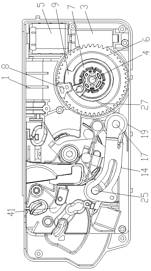
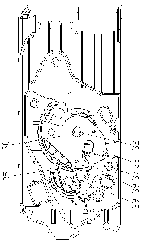
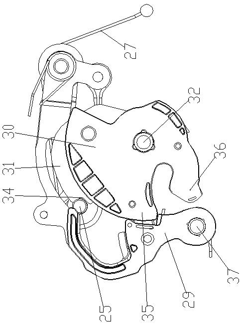
[0027] Such as Figure 1-9 As shown, the pulley block type electric vehicle door lock structure of the present invention includes a pawl support 1, the front and rear sides of the pawl support 1 are provided with installation cavities, and the installation cavity on the front side of the pawl support 1 is provided with an opening arm 2. The pulley assembly and the electric drive mechanism. The electric drive mechanism includes a worm 3, a turbine shaft 4 and a motor 5. The motor 5 is assembled on the right side of the claw support 1, and the worm 3 is rotatably connected to the right side of the claw support 1. The motor The main shaft of 5 is connected with the transmission of the worm 3, and the turbine shaft 4 is fixed on the claw support 1 along the front and rear horizontal direction and is located on the left side of the worm 3, and the turbine shaft 4 is connected with the turbine 6 and the suction wheel 7 in rotation, and the suction wheel 7 Located on the front side o...


PUM


Abstract

The invention provides a pulley block type electric automobile door lock structure. The pulley block type electric automobile door lock structure comprises a claw support. Mounting cavities are formedin the front side and the rear side of the claw support correspondingly. An opening arm, a pulley assembly and an electric driving mechanism are arranged in the mounting cavity in the front side of the claw support. The electric driving mechanism comprises a worm, a turbine shaft and a motor. The motor is assembled on the right side of the claw support. The worm is rotatably connected to the right side of the claw support. A spindle of the motor is in transmission connection with the worm. The turbine shaft is horizontally fixed to the claw support in the front-back direction and is located on the left side of the worm. A turbine and a closing wheel are rotatably connected to the turbine shaft. The closing wheel is located on the front side of the turbine. A lug is fixed to the front surface of the turbine. A push plate is fixed to the outer edge of the closing wheel. The lug is in transmission fit with the push plate when rotating clockwise. In conclusion, the pulley block type electric automobile door lock structure is reasonable in structural design, compact in overall layout, capable of saving space, safe, reliable, high in practicability and easy to apply and popularize and has a great market potential.

Description

technical field [0001] The invention belongs to the technical field of automobile door locks, and in particular relates to a pulley block type electric automobile door lock structure. Background technique [0002] With the development of automobile door locks to this day, the degree of electrical integration is getting higher and higher, and the volume is gradually developing in the direction of light weight. So how to use a more reasonable and convenient mechanism to achieve the same function for door locks with the same function, It is a development idea and direction of follow-up car door locks; as a self-priming and self-opening side door lock, most of the existing products on the market have the characteristics of large size, heavy weight, scattered layout, and high cost, and in order to achieve electric suction The closing conditions are often completed by using a large pull-in motor. [0003] For traditional door locks, to achieve electric pull-in and electric open, ...

Claims


Application Information

Patent Timeline
Patent Type & Authority Patents(China)
IPC IPC(8): E05B81/06E05B81/34E05B79/10E05B79/20
Inventor 方佳宁孙治国周明甫张春雷
Owner 方佳宁
Why Eureka
Try Eureka