Scroll compressor

A scroll compressor and compression mechanism technology, applied in the field of compressors, can solve problems such as increased internal leakage risk, aggravated compressor leakage, and decreased sealing performance, and achieve the goals of prolonging the pressure build-up time, eliminating internal leakage, and increasing assembly clearance Effect

Active Publication Date: 2018-10-02
WANBAO GROUP COMPRESSOR CO LTD
View PDF4 Cites 0 Cited by
  • Summary
  • Abstract
  • Description
  • Claims
  • Application Information

AI Technical Summary

Problems solved by technology

[0007] 2. When the long-term work between the movable scroll and the support, and between the movable scroll and the fixed scroll wears out, the sealing gap between the movable scroll and the fixed scroll will become larger, and the sealing performance will decrease , the leakage in the compressor is aggravated
[0008] 3. The medium-pressure cavity is formed by a combination of multiple parts, and there are many sealing lines, which greatly increase the risk of internal leakage
[0009] 4. Due to the existence of the medium pressure chamber, the ability of the inclined oil hole in the center of the crankshaft to pump lubricating oil is damaged by the reverse pressure difference

Method used


Image

  • Scroll compressor
  • Scroll compressor
  • Scroll compressor

Examples


Embodiment Construction

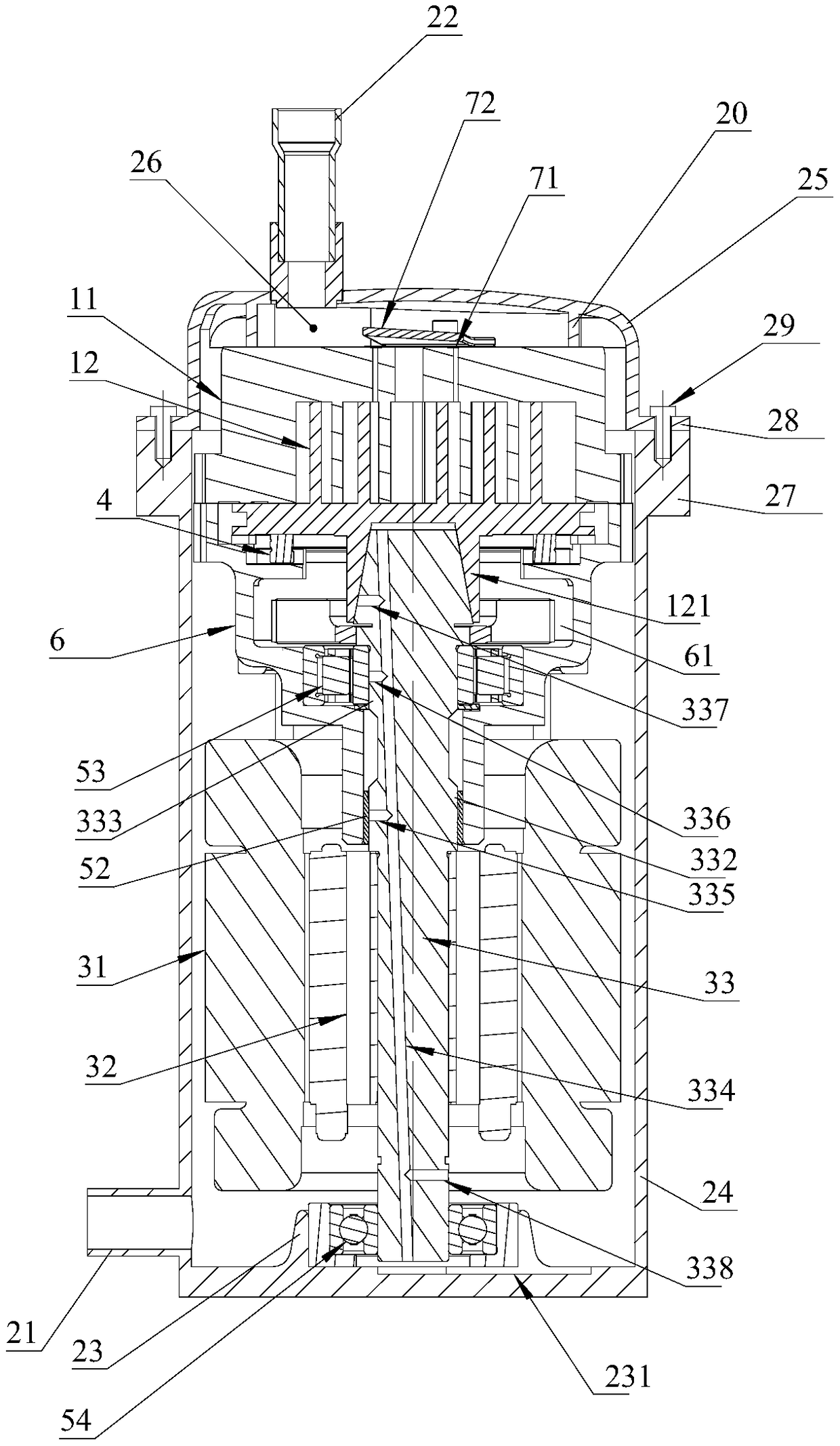
[0033] refer to Figure 1 to Figure 4 , which shows the specific structure of the preferred embodiment of the present invention. The structural features of each part of the present invention will be described in detail below, and if there is a description to the direction (up, down, left, right, front and back), it is based on figure 1 The shown structure is a reference description, but the actual use direction of the present invention is not limited thereto.

[0034] The present invention provides a scroll compressor, including a casing, a compression mechanism and a drive mechanism, the compression mechanism includes a fixed scroll 11 and a movable scroll 12, and the fixed scroll 11 and the movable scroll 12 cooperate A compression chamber is formed, and the casing has a suction pipe 21 communicating with the intake end of the compression chamber and an exhaust pipe 22 communicating with the exhaust end of the compression chamber. The drive mechanism includes a stator 31, a...


PUM


Abstract

The invention discloses a scroll compressor, belonging to the technical field of compressors. The scroll compressor comprises a shell, a compression mechanism and a driving mechanism. The compressionmechanism comprises a fixed scroll and an orbiting scroll, wherein the fixed scroll and the orbiting scroll cooperate with each other to form a compression chamber; the shell has an air suction pipe communicating with the air inlet end of the compression chamber and an air exhausting pipe communicating with the air exhausting end of the compression chamber; the driving mechanism comprises a stator, a rotor and a crankshaft connected with the rotor; the eccentric portion of the crankshaft is cooperated and connected with the orbiting scroll; the orbiting scroll has a cross slip ring and a driving seat; the driving seat is provided with a driving groove for embedding of the eccentric portion of the crankshaft; the driving groove has an inner conical surface; the eccentric portion of the crankshaft has an outer conical surface; and the inner conical surface and the outer conical surface cooperate with each other and provide an action force for pushing the orbiting scroll toward the fixedscroll. The scroll compressor of the invention adopts the design of no medium-pressure chamber, so the problem of leakage is overcome, the sealing performance of an end face is ensured, self-protection effect is obtained, and technical problems in the prior art are solved.

Description

technical field [0001] The invention is used in the technical field of compressors, and in particular relates to a scroll compressor. Background technique [0002] In the existing semi-hermetic scroll compressor, an air suction passage is arranged on the shell, and the inside of the shell is a low-pressure chamber. The end of the shell is fastened to the end cover by the connecting structure. A sealing structure is set between the end cover and the fixed scroll to form a high-pressure chamber. The fixed scroll and the movable scroll in the scroll compressor are two involute scrolls with the same shape but staggered by 180° relative to each other. Among them, the fixed scroll is fixed on the shell, and the movable scroll is driven by the eccentric shaft, and its axis revolves around the rotation axis. When the scroll compressor is working, the worm teeth of the two scrolls are tangentially engaged in many places to form a sealing line, and the proper sealing at the end fac...

Claims


Application Information

Patent Timeline
Patent Type & Authority Applications(China)
IPC IPC(8): F04C18/02F04C29/00F04C29/02F04C29/12
CPCF04C18/0215F04C29/0042F04C29/02F04C29/12F04C2240/50
Inventor 陈会平相玲玲李顺林香
Owner WANBAO GROUP COMPRESSOR CO LTD
Why Eureka
Try Eureka