Torque-limited speed reducer

A technology of reducer and planetary reducer, which is applied to transmission parts, belts/chains/gears, mechanical equipment, etc. It can solve problems such as complex maintenance and repair, shutdown of working face, broken teeth of reducer, etc., to ensure continuous Work, save space, protect the effect of the motor and reducer

Pending Publication Date: 2018-10-02
山西煤矿机械制造股份有限公司
View PDF0 Cites 0 Cited by
  • Summary
  • Abstract
  • Description
  • Claims
  • Application Information

AI Technical Summary

Problems solved by technology

The inside of the traditional reducer is hard-connected. When a special situation occurs and the output end is stuck, the motor will usually be burned out, or the gear of the reducer will be broken directly, resulting in the shutdown of the working face.
[0004] The Controlled Start Transmission (CST) reducer has the function of torque limiting protection, but it is bulky, and its torque limiting device is located inside the reducer, which involves more complicated structural forms such as cooling and sealing, and its price is much higher than that of the same type of reducer. Maintenance and repair are quite complicated, and the maintenance cycle is long

Method used


Image

  • Torque-limited speed reducer
  • Torque-limited speed reducer
  • Torque-limited speed reducer

Examples


Embodiment 1

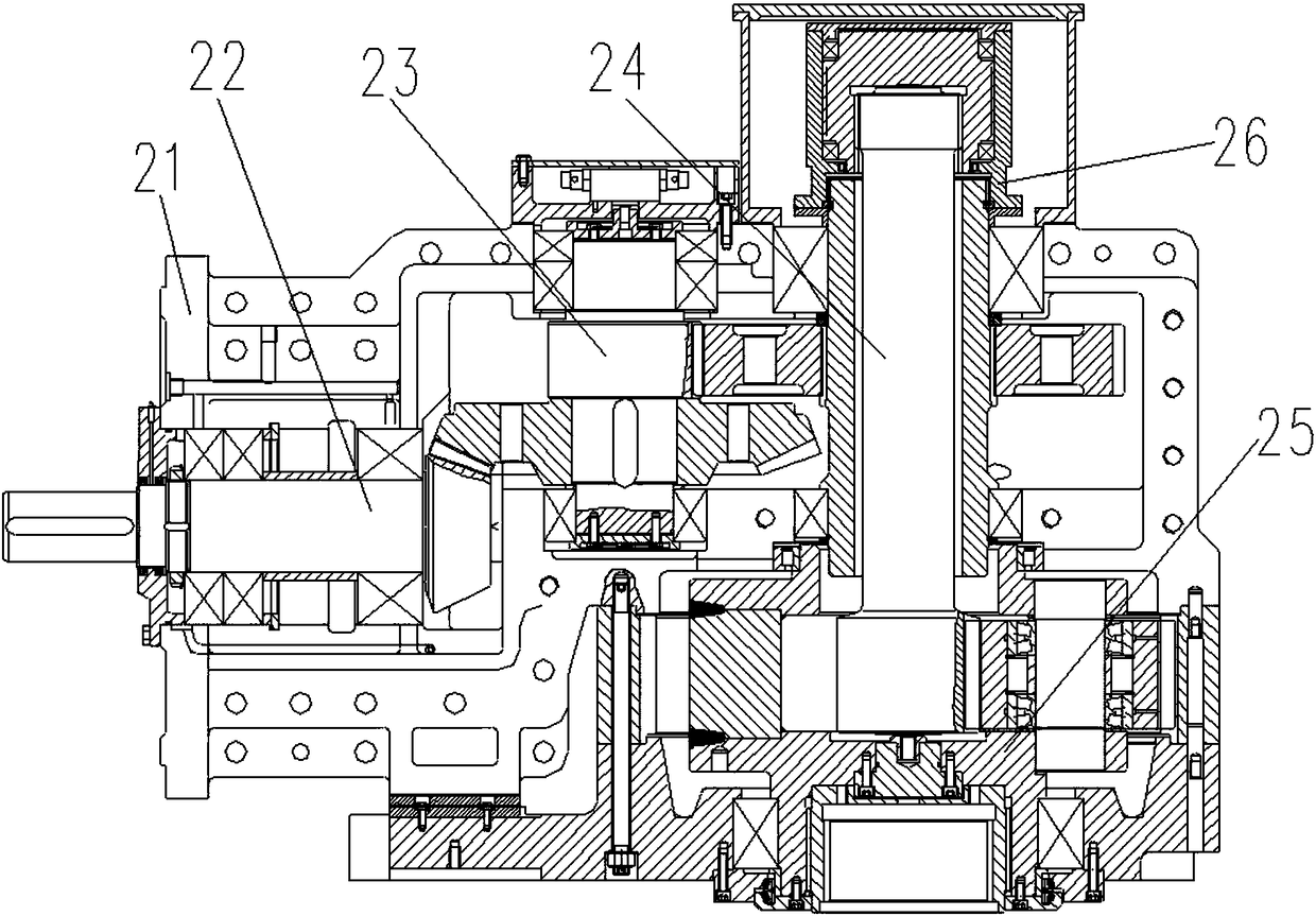
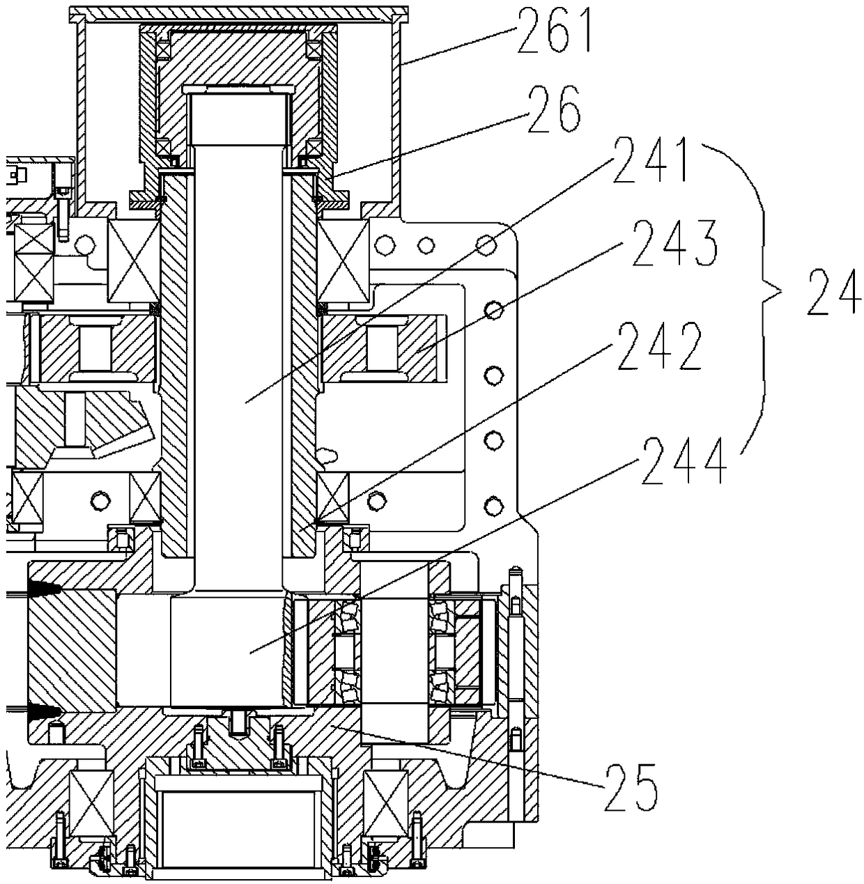
[0034] When the torque-limiting reducer of Embodiment 1 is in normal operation, the motor at the power input end drives the drive wheel on the passive side of the first-axis assembly 2 to rotate, and the drive wheel on the passive side of the first-axis assembly 22 drives the drive wheel on the driving side of the second-axis assembly 23 to rotate. , the driven side transmission wheel of the two-axis assembly 23 drives the driving side transmission wheel of the three-axis assembly 24 to rotate, and the shaft sleeve 242 connected to the active side transmission wheel of the three-axis assembly 24 rotates synchronously, and drives the shaft 241 and the sun gear 244 to rotate , and then the sun gear 244 drives the planetary gears in the output assembly to rotate. When the output end of the reducer is stuck and stalled, the output end stops rotating, while the motor at the input end runs normally. When the torque difference between the input and output exceeds the maximum torque se...

Embodiment 2

[0035] The main difference between the structure of the torque-limiting reducer provided in Embodiment 2 and the structure of the torque-limiting reducer in Embodiment 1 is that the shaft assembly connected to the torque-limiting device 26 at the shaft end is the two-axis assembly 23 in the planetary reducer. In the torque-limiting reducer of Embodiment 2, the two-shaft assembly 23 includes a shaft and a shaft sleeve. The outer periphery of the shaft sleeve is provided with a driving side drive wheel, and the part of the shaft exposed from the end of the shaft sleeve away from the torque limiting device 26 is provided with a passive gear. Side drive wheels. The torque-limiting reducer of Embodiment 2 also includes a shaft assembly 22 and a three-shaft assembly 24, the driving side drive wheel of the two-shaft assembly 23 is connected to the power input end through the first shaft assembly 22, and the passive side transmission wheel of the two-shaft assembly 23 It is connected ...


PUM


Abstract

The invention provides a torque-limited speed reducer. The torque-limited speed reducer comprises a box body, a shaft assembly which is at least partially located in the box body, and a torque-limiteddevice which is located outside the box body. The shaft assembly comprises a shaft rod and a shaft sleeve with which the shaft rod is sleeved. One end of the shaft rod and one end of the shaft sleeveextend out of the box body to be connected with a first portion and a second portion of the torque-limited device correspondingly. When the relative torque, between the shaft rod and the shaft sleeve, of the first portion and the second portion of the torque-limited device is smaller than or equal to the maximum set torque, the shaft rod and the shaft sleeve are enabled to rotate synchronously, and when the relative torque between the shaft rod and the shaft sleeve is larger than the maximum set torque, slipping occurs between the shaft rod and the shaft sleeve. A driving side transmission wheel is disposed on the periphery of the shaft sleeve, and the portion, which is exposed out of the end, far away from the torque-limited device, of the shaft sleeve, of the shaft rod is provided witha driven side transmission wheel. The motive power action of the motive power input end is applied to the driving side transmission wheel, and the driven side transmission wheel exerts the motive power action on the motive power output end. The torque-limited speed reducer is compact and simple in structure, easy to operate, safe and reliable during operation, and good in torque-limited function.

Description

technical field [0001] The invention relates to the technical field of underground coal mines, mines and other heavy matching reducer equipment, in particular to a torque-limiting reducer. Background technique [0002] Coal mining and transportation in the fully mechanized mining face of the coal mine mostly use conveyors such as loaders and scraper conveyors. [0003] figure 1 A structural schematic diagram of an existing reducer is provided as an example. like figure 1 As shown, this existing speed reducer includes a casing 11 and a shaft assembly 12, a second shaft assembly 13, a three-shaft assembly 14, and a sun gear 15 at least partially located in the casing 11, and the power of the motor at the power input end passes through The first shaft assembly 12, the second shaft assembly 13, the three shaft assembly 14 and the sun gear 15 are transmitted to the power output end step by step. The shaft of the triaxial assembly 14 and the shaft of the sun gear 15 are spaced...

Claims


Application Information

Patent Timeline
Patent Type & Authority Applications(China)
IPC IPC(8): F16H35/10F16H57/00
CPCF16H35/10F16H57/0018F16H2035/103
Inventor 樊建军刘卫东谢地文卫星高丽霞逯盛华
Owner 山西煤矿机械制造股份有限公司
Why Eureka
Try Eureka