
Water pipe valve control device

A technology for valve control and water pipes, applied to valve devices, valve operating/release devices, cocks including cut-off devices, etc., can solve problems such as changes, low work efficiency, inconvenient operation, etc., to simplify the overall structure and improve work efficiency , Easy to open the effect

Inactive Publication Date: 2018-10-02
陈景芳
View PDF0 Cites 2 Cited by
  • Summary
  • Abstract
  • Description
  • Claims
  • Application Information

AI Technical Summary

Problems solved by technology

[0003] The technical problem to be solved by the present invention is: in order to solve the problem that the internal pressure of the high-pressure water pipe often changes, making the internal flow of the high-pressure water pipe unstable, which is not conducive to normal water use; through the manual control of the ball valve in the water pipe pipeline, it is inconvenient to operate when operating multiple ball valves. The efficiency is low; the pressure difference between the two sides of the ball valve spool in the high-pressure water pipeline is large, and it is difficult to open the ball valve, which is not conducive to the use of the valve. The water channel, the pressure change inside the water pipe line, the different pressure and the side of the valve plate, the valve plate moves through the spring control to control the size of the hole between the valve plate and the valve core, and controls the flow of the water channel in the middle of the valve core, so that The flow in the water pipe is stable and plays the role of stabilizing the pressure; the drive motor is used to jointly control the opening and closing of the valve core and the control valve core, and the hydraulic cylinder controls the drive motor to drive the control valve core, which improves work efficiency and simplifies the overall structure ;The connecting pipe is used to balance the water pressure on both sides of the valve core before opening the valve core, so that the valve core can be opened smoothly and the drive motor can drive the valve core to open smoothly

Method used


Image

  • Water pipe valve control device
  • Water pipe valve control device
  • Water pipe valve control device

Examples


Embodiment Construction

[0020] The present invention is described in further detail now in conjunction with accompanying drawing. These drawings are all simplified schematic diagrams, which only illustrate the basic structure of the present invention in a schematic manner, so they only show the configurations related to the present invention.

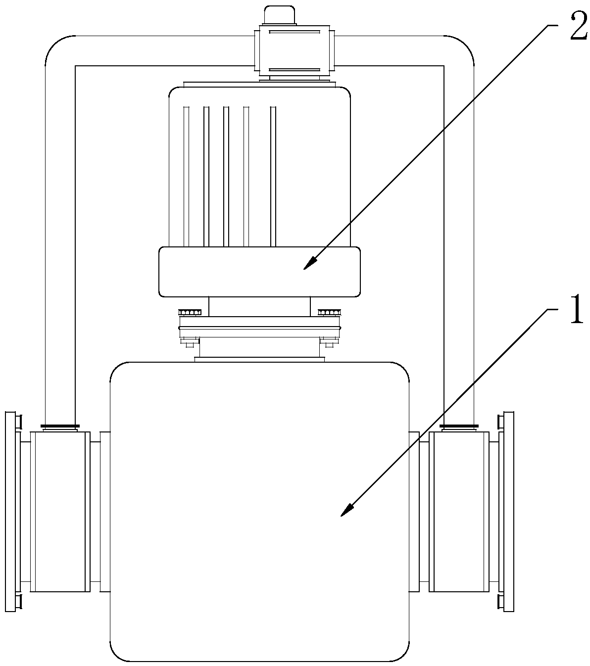
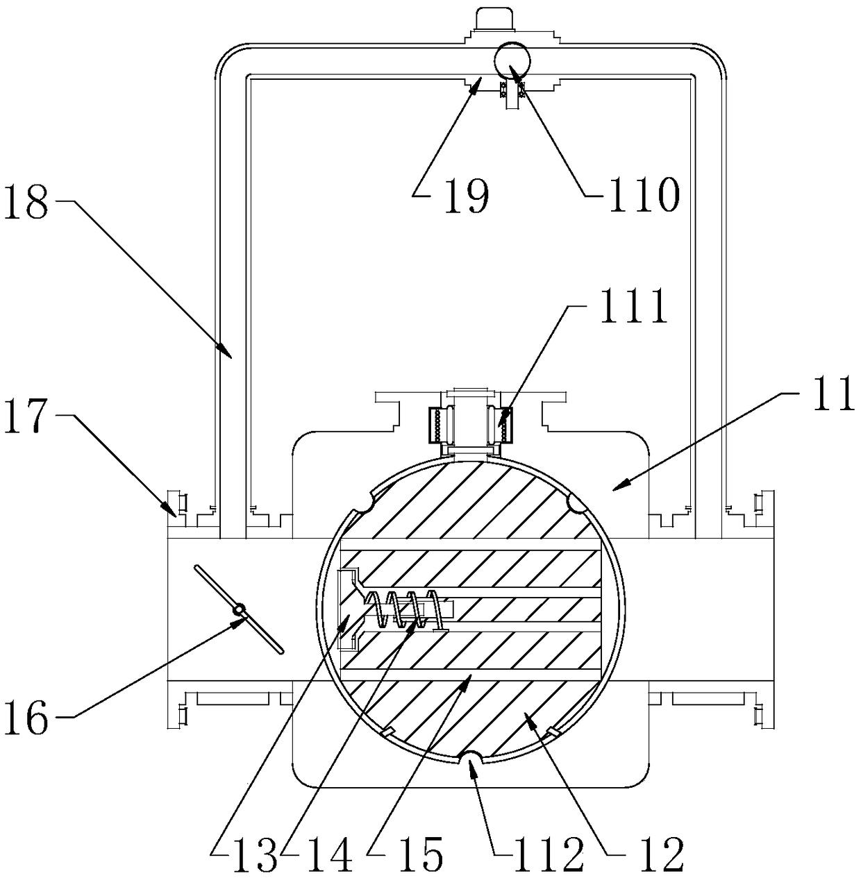
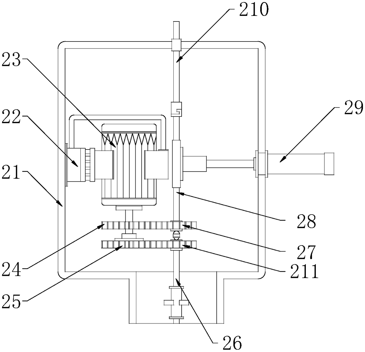
[0021] Such as Figure 1-Figure 3 As shown, a water pipe valve control device includes a water control mechanism 1 and a valve control mechanism 2, and the top of the water control mechanism 1 is vertically installed with a valve control mechanism 2, which is characterized in that:

[0022] The water control mechanism 1 includes a valve body 11, a valve core 12, a valve cover 13, a spring 14, a water passage 15, a communication pipe 18, a control valve body 19 and a control valve core 110, and the valve core 12 is fitted inside the valve body 11 The installation chamber of the spool 12 is provided with horizontal water passages 15 at equidistant intervals ins...


PUM


Abstract

The invention relates to the technical field of novel water valve devices, in particular to a water pipe valve control device which comprises a water control mechanism and a valve control mechanism, wherein the valve control mechanism is vertically mounted at the top of the water control mechanism. The water pipe valve control device has the beneficial effects that a water passing channel positioned at the middle of a valve core is controlled by adopting a valve plate; the internal pressure of a water pipe changes and different pressure is applied to one side of the valve plate; the valve plate is controlled by a spring to move, so that the size of a hole between the valve plate and the valve core can be controlled, the flow rate of the water passing channel positioned at the middle of thevalve core can be controlled, the internal flow rate of the water pipe can be stabilized, and the pressure stabilizing effect can be achieved; the valve core and a control valve core are jointly controlled by adopting a driving motor to open and close as well as the driving motor is controlled by a hydraulic cylinder to drive the control valve core, so that the working efficiency can be improvedand the whole structure can be simplified; and the water pressure on two sides of the valve core is balanced by adopting a communicating pipe before the valve core is opened, so that the smooth opening of the valve core can be facilitated and the valve core can be smoothly driven by the driving motor to open.

Description

technical field [0001] The invention relates to the technical field of novel water valve devices, in particular to a water pipe valve control device. Background technique [0002] The ball valve came out in the 1950s. With the rapid development of science and technology, the continuous improvement of production technology and product structure, it has rapidly developed into a major valve category in just 40 years. In western industrially developed countries, the use of ball valves is increasing year by year. In my country, ball valves are widely used in petroleum refining, long-distance pipelines, chemicals, papermaking, pharmaceuticals, water conservancy, electric power, municipal, steel and other industries. occupies a pivotal position in the national economy. Ball valves are widely used in water pipes, especially in high-pressure water pipes. The internal pressure of high-pressure water pipes often changes, making the internal flow of high-pressure water pipes unstable, w...

Claims


Application Information

Patent Timeline
Patent Type & Authority Applications(China)
IPC IPC(8): F16K5/08F16K31/53F16K31/36
CPCF16K5/08F16K31/36F16K31/535
Inventor 陈景芳
Owner 陈景芳
Learn More