Safety lamp holder

A safety lamp cap and lamp cap technology, which is applied to lighting devices, lighting device parts, lighting auxiliary devices, etc., can solve the problem of increasing the structural complexity and design difficulty of the lamp cap, increasing the production, use and maintenance costs of the lamp cap, and limiting the lighting angle of the lamp. It can achieve the effect of rich practical functions, avoiding the complex structure of lamp caps, strong practical value and market promotion value.

Pending Publication Date: 2018-10-02
何秀华
View PDF1 Cites 1 Cited by
  • Summary
  • Abstract
  • Description
  • Claims
  • Application Information

AI Technical Summary

Problems solved by technology

[0004] 1. It uses an integrated switching power supply as the switch device in the lamp head. When the second switch assembly is inserted into the lamp tube along the radial direction of the lamp tube, the end of the second switch assembly will trigger the switch in a sideways manner. The switch contact of the power supply, so as to turn on the power switch; this method not only needs to arrange an electrical connection line between the pins of the lamp tube and the switching power supply, thereby increasing the disassembly process and failure points of the lamp holder, but also because the switching power supply It has a large space volume and specific structural dimensions, which will make the internal space of the lamp holder extremely cramped, increase the complexity of the lamp holder structure and design difficulty; in addition, the use of switching power supply will also greatly increase the production, use and maintenance of the entire lamp holder. maintenance cost
[0005] 2. Once the lamp cap and the main body of the lamp tube are assembled, the main body of the lamp tube cannot adjust the angle relationship relative to the lamp cap, which greatly limits the user's demand for adjusting the light emitting angle of the lamp

Method used


Image

  • Safety lamp holder
  • Safety lamp holder
  • Safety lamp holder

Examples


Embodiment Construction

[0041] The embodiments of the present invention will be described in detail below with reference to the accompanying drawings, but the present invention can be implemented in many different ways defined and covered by the claims.

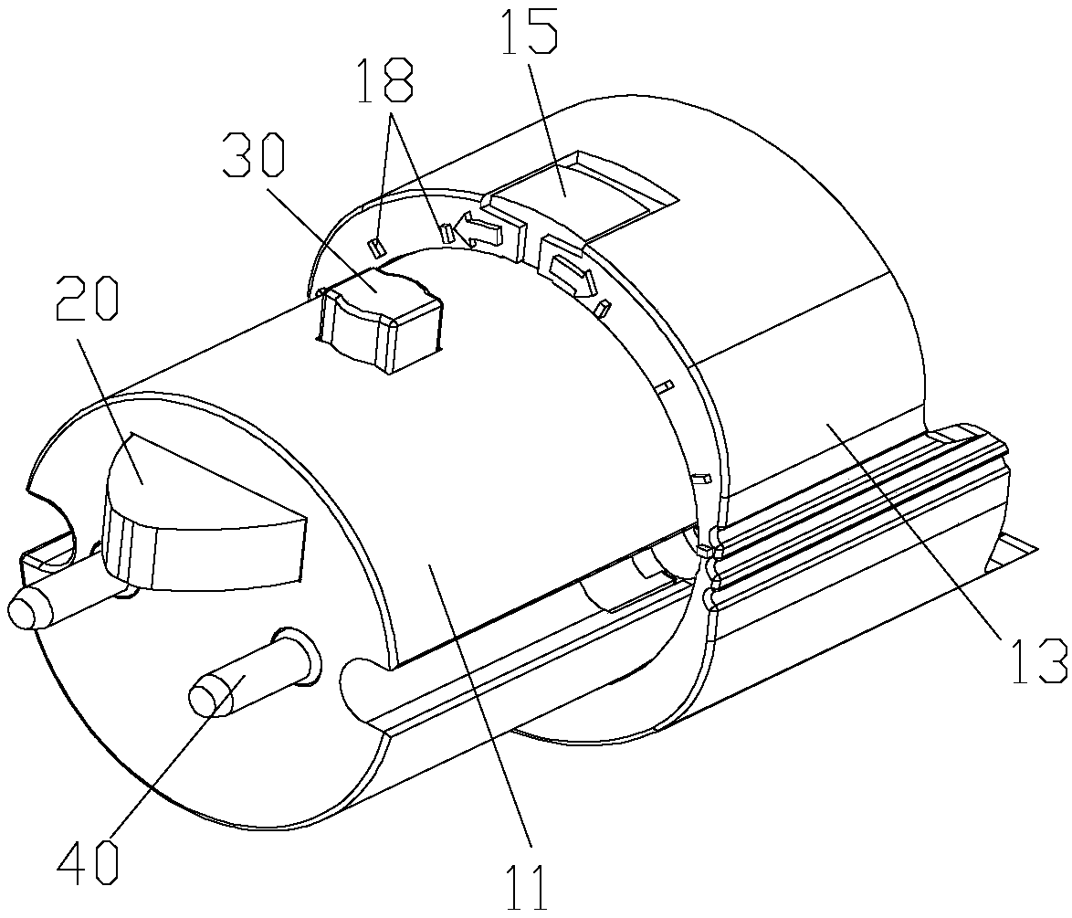
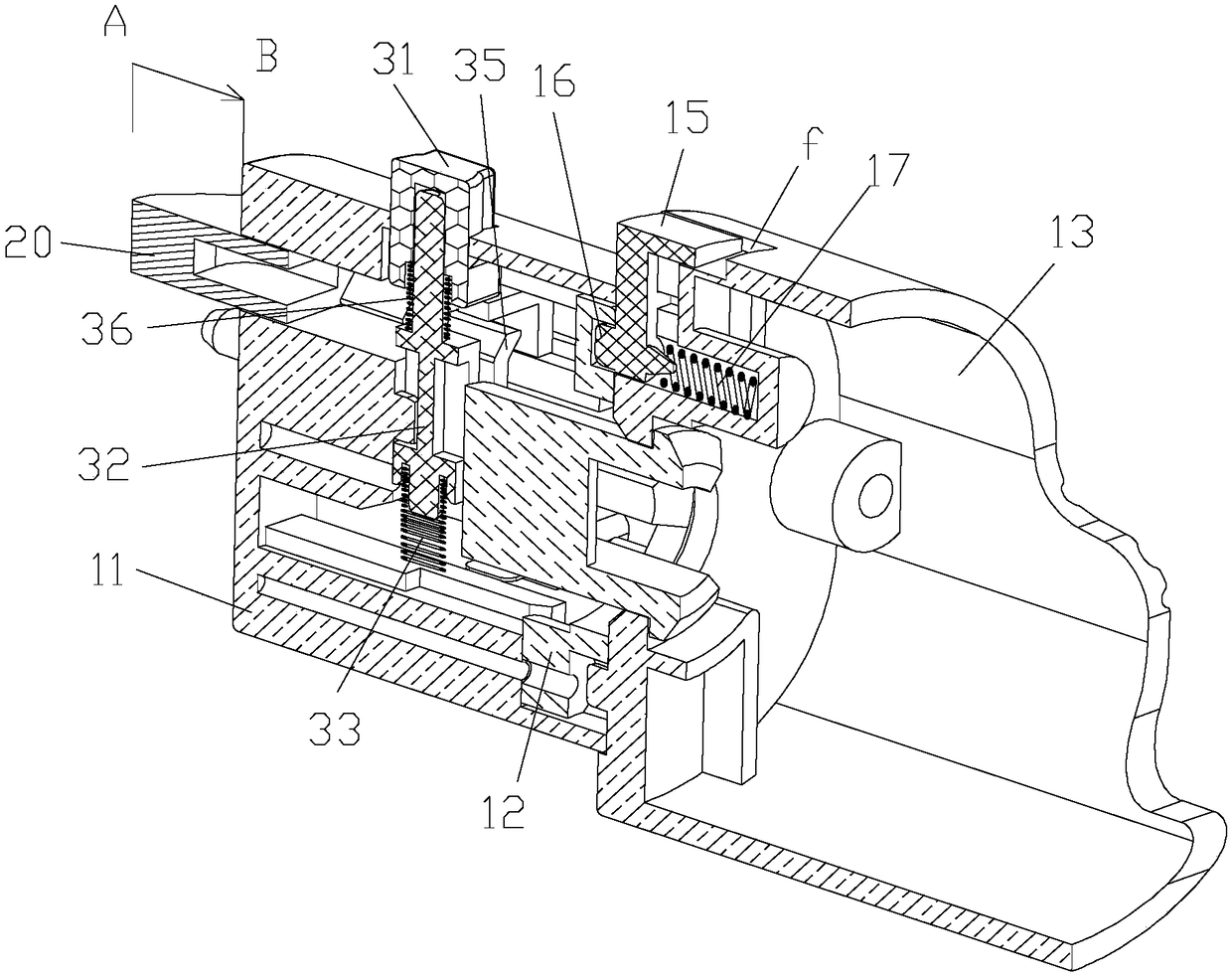
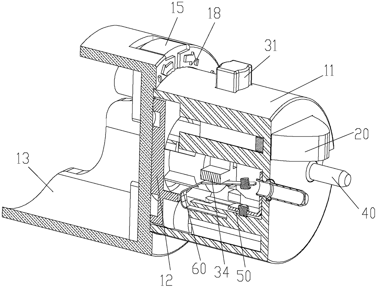
[0042] Such as Figure 1 to Figure 9 As shown, the present embodiment provides a safety lamp cap, which includes:

[0043] A lamp head body 10, which is a tubular structure with an inner cavity structure;

[0044] A safety button 20, the main body of which is inserted into the lamp body 10 by the front end surface of the lamp body 10 and can be positioned between the locking position A and the unlocking position B along the axial direction of the lamp body 10 when the pressure is applied or the pressure is released. Make reciprocating motions; at the same time, a stop lock a is provided on the main body part of the safety button 20 (that is, the part inside the lamp head body 10);

[0045] A switch button 30, the main part of which is inserted int...


PUM


Abstract

The invention relates to the technical field of an illuminating lamp, in particular to a safety lamp holder. The safety lamp holder comprises a lamp holder body, a safety button, a switch button, a probe pin, a static conductive contact piece and a dynamic conductive contact piece, wherein the safety button does reciprocating motion along the axial direction of the lamp holder body, and the switchbutton does reciprocating motion along the radial direction of the lamp holder body; the probe pin is inserted into the lamp holder body along the axial direction of the lamp holder body, and the static conductive contact piece is connected with the inner end of the probe pin in one; the dynamic conductive contact piece is suspended above the static conductive contact piece. A stopping locking notch used for enabling the switch button to penetrate is formed in the main body part of the safety button. The safety button limits the switch button through the stopping locking notch so that the dynamic conductive contact piece and the static conductive contact piece are butted and contacted or separated. By the matching of the dynamic conductive contact piece and the static conductive contact piece, the safety lamp holder can ensure the conduction precision and stability of the probe pin and can evade a series of problems of complex lamp holder structure, high production and maintenance cost and complex line connection caused by adopting a switching power supply.

Description

technical field [0001] The invention relates to the technical field of lighting fixtures, in particular to a safety lamp holder. Background technique [0002] As we all know, the lamp holder generally refers to the lamp interface part installed on the lamp to connect the light source and the external power supply. Taking the existing straight tube lamp (such as T8 lamp tube and LED fluorescent lamp tube) as an example, the lamp tube passes through its two After the lamp cap at the end is energized, the lamp tube will emit light, and the lamp cap mainly plays the role of supporting the main body of the lamp tube and sealing the electrical connection of the lamp tube; And there is the risk of electric shock, which constitutes a great potential safety hazard to people. In view of this, there are some safety lamps on the market at present, which generally realize the conduction between the light source and the external power supply by adding a push switch on the lamp head. This...

Claims


Application Information

Patent Timeline
Patent Type & Authority Applications(China)
IPC IPC(8): F21V21/002F21V23/04
CPCF21V21/002F21V23/04
Inventor 何秀华
Owner 何秀华
Why Eureka
Try Eureka