Visual device with oblique cambered surface and variable channel

A flow channel and variable technology, applied in measuring devices, components using electrical devices, thermometers, etc., can solve the problems of inability to adjust the flow field structure and gap size, and achieve accurate and reliable visual measurement, shorten the cycle, and reduce costs. Effect

Active Publication Date: 2018-10-02
NUCLEAR POWER INSTITUTE OF CHINA
View PDF7 Cites 1 Cited by
  • Summary
  • Abstract
  • Description
  • Claims
  • Application Information

AI Technical Summary

Problems solved by technology

The device has simple structure, reasonable design, and good visualization effect, but the flow field of the fluid in the device has been fixed on the pole plate, and the flow field structure and gap size cannot be adjusted

Method used


Image

  • Visual device with oblique cambered surface and variable channel
  • Visual device with oblique cambered surface and variable channel

Examples


Embodiment 1

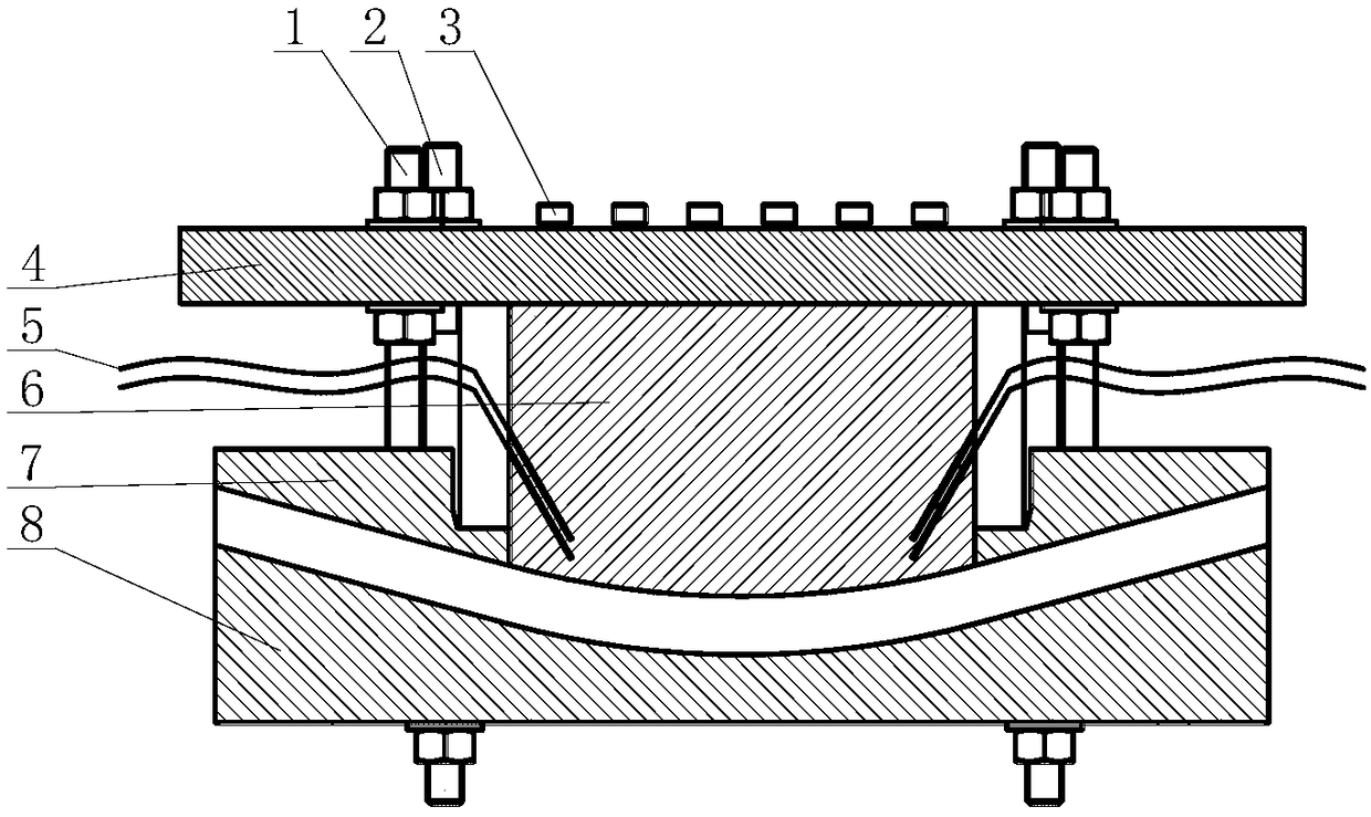
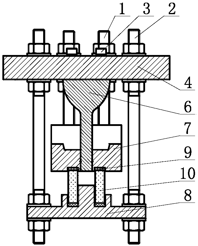
[0031] See attached figure 1 , attached figure 2 , first install the positioning plate 4 on the external rotating bracket; then screw a set of screws 3 downward from the top of the positioning plate 4 to connect the heating element 6; then screw the studs of a set of bolt combination I1 into the top shape plate 7 Corresponding to the assembly hole, insert the studs of the bolt combination I1 into the positioning plate 4 from the bottom of the positioning plate 4 after assembly, tighten the nuts and adjust the relative position of the upper shape plate 7; then fix the bolt combination II2 on the positioning plate 4 , connect the lower shape plate 8 with the bolt combination II2, and reserve enough space; then put the sealing gasket 9 into the sealing groove of the lower shape plate 8, and put the glass 10 in the sealing groove with the sealing gasket 9 , place another group of gaskets 9 on the other end of the glass 10; then gradually adjust the assembly position of the nut a...


PUM


Abstract

The invention discloses a visual device with an oblique cambered surface and a variable channel. The device comprises the components of a bolt assembly I, a bolt assembly II, a fixing board, a thermocouple, a heating member, an upper shaped board, a lower shaped board, a sealing gasket and glass. The heating member is fixed to the fixing board. The bolt assembly I fixes the upper shaped board to the fixing board. The sealing gasket is mounted in sealing troughs of the upper shaped board and the lower shaped board. The glass is mounted in a sealing trough with a gasket. The bolt assembly II isconnected with the lower shaped board and the fixing board. The thermocouple is obliquely mounted on an oblique hole of the heating member from the outside space of the device. One side, which is farfrom the glass, of the sealing gasket is provided with a metal gasket for adjusting the size of a channel gap, wherein the relative height of the upper shaped board is adjustable, the assembling position of the glass is adjustable, the inclination angle of the fixing board is adjustable, and the shape of the channel between the upper shaped board and the lower shaped board is adjustable. The visual device can realize continuous adjustment of the inclination angle in a scope ranging from -90 DEG to 90 DEG.

Description

technical field [0001] The invention relates to the technical field of vapor-liquid two-phase flow experiments, in particular to a visualization device for a variable flow path with an inclined arc surface. Background technique [0002] One of the key measures taken by the third-generation nuclear energy system to deal with severe meltdown accidents is to realize the retention of molten material in the reactor through external cooling of the reactor pressure vessel to ensure the integrity of the pressure vessel. The external cooling process of the reactor pressure vessel involves the flow and heat transfer process outside the inclined arc wall, and the boiling flow channel includes arc or semi-arc and semi-linear. Therefore, in order to obtain the vapor-liquid two-phase boiling flow in the external cooling process of the reactor pressure vessel In this situation, it is necessary to develop a visualization device for simulating and observing the direct image data of vapor-liq...

Claims


Application Information

Patent Timeline
Patent Type & Authority Applications(China)
IPC IPC(8): G01K7/02G01K1/14G01K1/08
Inventor 肖仁杰张震张君毅昝元锋闫晓
Owner NUCLEAR POWER INSTITUTE OF CHINA
Why Eureka
Try Eureka