Rolling vibration experiment platform

An experimental platform, magnetic powder brake technology, applied in vibration testing, measuring devices, testing of machine/structural components, etc., can solve the problems of inability to study the rolling vibration mechanism and the effect and effect of rolling stock forming quality.

Active Publication Date: 2018-10-02
HENAN POLYTECHNIC UNIV
View PDF13 Cites 7 Cited by
  • Summary
  • Abstract
  • Description
  • Claims
  • Application Information

AI Technical Summary

Problems solved by technology

[0006] The above inventions all focus on the detection and suppression of rolling mill vibration, which are post-event and passive. None of these inventions can study the mechanism of rolling vibration and its influence and effect on the forming quality of rolled products.

Method used


Image

  • Rolling vibration experiment platform
  • Rolling vibration experiment platform
  • Rolling vibration experiment platform

Examples


Embodiment 1

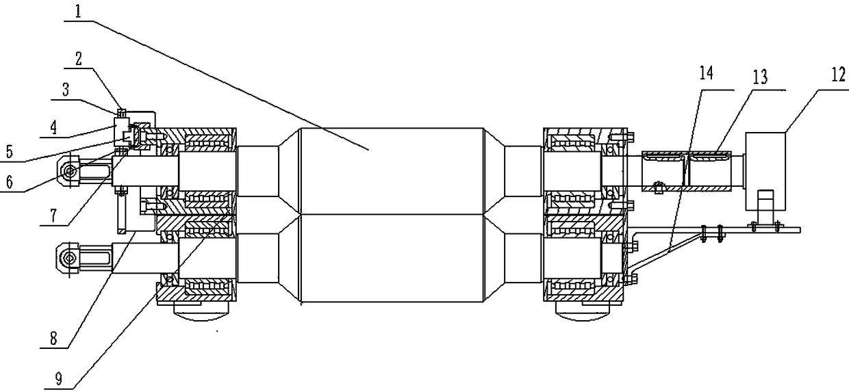
[0034] The rolling vibration experiment platform adopted in this embodiment, such as figure 1 shown. The rolling vibration experiment platform includes an upper work roll 1, and the upper work roll 1 includes a transmission side shaft end located at the left end and an operation side shaft end located at the right end, and a control shaft end of the upper work roll is arranged on the transmission side shaft end. The radial vibration exciter 4 is connected to the shaft end of the operation side with a magnetic powder brake 12 that controls the torsional vibration of the upper work roll in the circumferential direction, and the magnetic powder brake 12 is coaxially arranged with the upper work roll 1 . When working, the exciter 4 is cleverly used to realize the radial vibration of the upper work roll, and the magnetic powder brake 12 is used to realize the torsional vibration of the upper work roll along the circumferential direction. The output shaft of the magnetic powder bra...

Embodiment 2

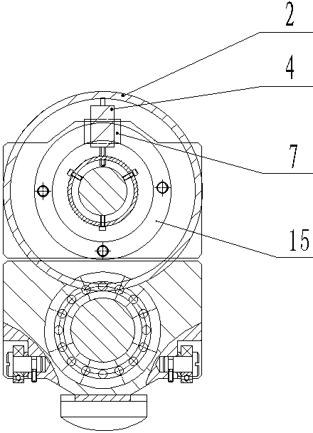
[0042] In this example, if Image 6 As shown, on the basis of Embodiment 1, two guide rail sliders 7 are provided on the annular guide rail 15 along the circumferential direction, and the guide rail sliders 7 are equipped with exciters 4, and the two exciters are in the The included angle of the central angle on the circumference is 90°, which is set as a horizontal vibrator 41 for controlling the horizontal vibration of the upper work roll 1 and a vertical vibrator 42 for controlling the vertical vibration of the upper work roll 1 . The exciter base 5 is fixed on the corresponding guide rail slider 7, and a clamp 6 is fixed at the shaft end of the transmission side, and a reserved hole is set on the clamp 6, and the ejector rod of the exciter 4 passes through The corresponding reserved holes are in contact with the peripheral surface of the transmission side shaft end to realize the synchronous rotation of the vibrator 4 and the upper work roll 1, and ensure that the ejector ...

Embodiment 3

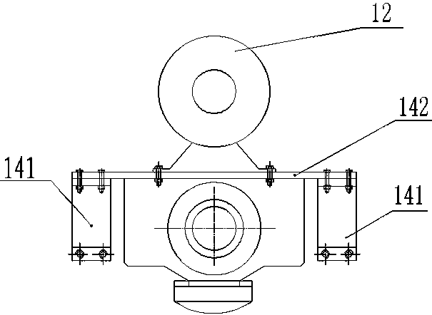
[0046] In this example, if Figure 7 As shown, on the basis of Example 2, the operating side shaft end and the magnetic powder brake 12 are connected through the coaxially arranged connecting shaft 10, and the experimental conditions are as close as possible to the actual production conditions without changing the original rolling mill structure. same. Preferably, the sleeve coupling includes a first sleeve coupling 13 and a second sleeve coupling 11, and the left end of the connecting shaft 10 is connected to the operating side shaft through the first sleeve coupling 13. The right end of the connecting shaft 10 is coaxially connected with the magnetic powder brake 12 through the second sleeve coupling 11, which improves the fixed connection effect between the connecting shaft 10 and the operating side shaft end and the magnetic powder brake 12. At the same time, as far as possible It is possible to simulate the actual working state, and provide effective experimental data fo...


PUM


Abstract

The invention relates to a rolling vibration experimental platform, and belongs to the technical field of rolling vibration detection and experimental demonstration. The rolling vibration experimentalplatform includes an upper working roller; the upper working roller comprises a transmission side shaft end at a left end portion and an operation side shaft end at a right end portion; the transmission side shaft end is provided with at least one exciter for controlling the radial vibration of the upper working roller; the operation side shaft end is connected to a magnetic powder brake for controlling the torsional vibration of the upper working roller in the circumferential direction; and the magnetic powder brake is disposed coaxially with the upper working roller. The rolling vibration experimental platform can realize the radial vibration and torsional vibration of the upper working roller of a rolling mill; several vibration types can be independent of each other, and can form several combinations as needed; the experimental platform can achieve independent vibration and coupled vibration of torsional, vertical and horizontal vibration of the working roller, can reveal the internal mechanism and influence law of rolling vibration, can clarify the relationship between the quality of rolled products and rolling vibration, and can provide effective experimental data for the above research.

Description

technical field [0001] The invention belongs to the technical field of rolling vibration detection and experiment demonstration, and in particular relates to a rolling vibration experiment platform. Background technique [0002] Rolling vibration is a major technical problem plaguing iron and steel enterprises worldwide. On the one hand, it forms light and dark stripes on the surface of the strip product, which increases the thickness error of the strip and affects product quality; on the other hand, the severe vibration of the rolling mill may cause strip breakage or equipment damage accidents. How to effectively reveal the internal influence law of rolling vibration is the key to controlling the quality of rolled products. [0003] Many researchers have done a lot of work on various vibrations produced by rolling mills during work. Chinese invention patent "Measurement device for vertical vibration of electromechanical-hydraulic coupling of rolling mill reduction system"...

Claims


Application Information

Patent Timeline
Patent Type & Authority Applications(China)
IPC IPC(8): G01M7/06G01M7/02
CPCG01M7/022G01M7/06
Inventor 赵武刘志伟黄丹张鸿斌李书博
Owner HENAN POLYTECHNIC UNIV
Why Eureka
Try Eureka