Demoulding device and demoulding method of magnetic material

A magnetic material and demoulding device technology, applied in the manufacture of inductors/transformers/magnets, electrical components, circuits, etc., can solve the problems of low demoulding efficiency and achieve the effect of easy installation and processing

Active Publication Date: 2018-10-02
ZHEJIANG NANCI IND CO LTD
View PDF9 Cites 0 Cited by
  • Summary
  • Abstract
  • Description
  • Claims
  • Application Information

AI Technical Summary

Problems solved by technology

This invention cannot use the material's own inertia and vibration to achieve demoulding, so the demoulding efficiency is low

Method used


Image

  • Demoulding device and demoulding method of magnetic material
  • Demoulding device and demoulding method of magnetic material
  • Demoulding device and demoulding method of magnetic material

Examples


specific Embodiment approach 1

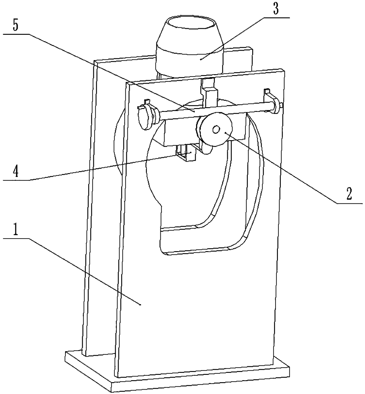
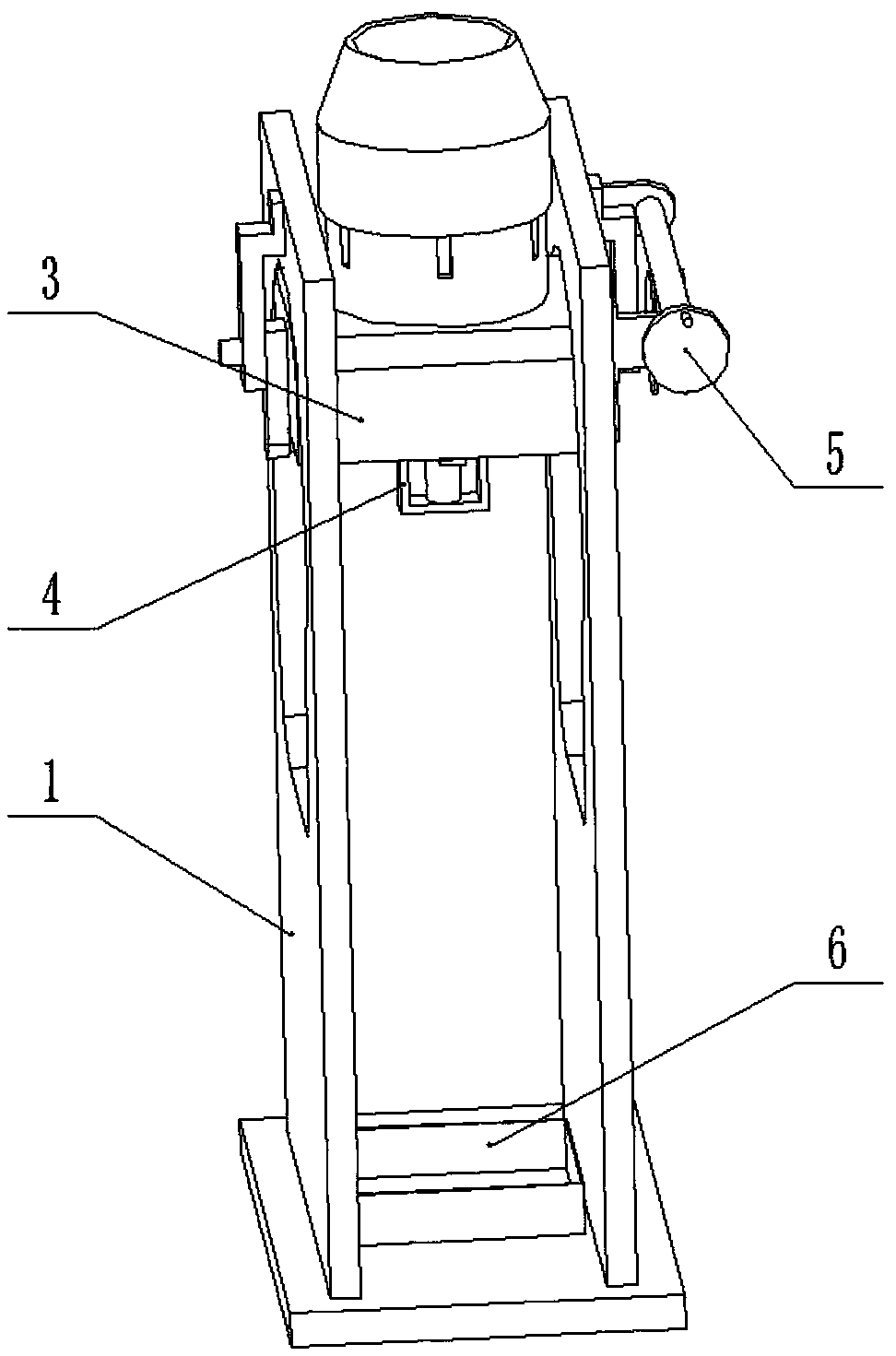
[0031] Combine below Figure 1-11 Describe this embodiment, a magnetic material demoulding device, including a frame 1, a worm gear assembly 2, a mold fixture 3, a pushing device 4 and a worm assembly 5, the worm gear assembly 2 is rotatably connected to the frame 1, the The mold fixing part 3 is arranged at the middle end of the worm gear assembly 2, the pushing device 4 is fixedly connected to the worm gear assembly 2, the pushing device 4 elastically squeezes the mold fixing part 3, and the mold fixing part 3 is slidably connected On the frame 1, the worm assembly 5 is rotatably connected to the frame 1, and the worm assembly 5 and the worm assembly 2 are engaged and connected through the worm gear; when in use, the mold is fixed in the mold fixture 3, and the worm is manually operated The component 5 drives the worm gear component 2 to rotate, and the rotation of the worm gear component 2 drives the mold fixing part 3 to turn over. When the opening of the mold fixing part ...

specific Embodiment approach 2

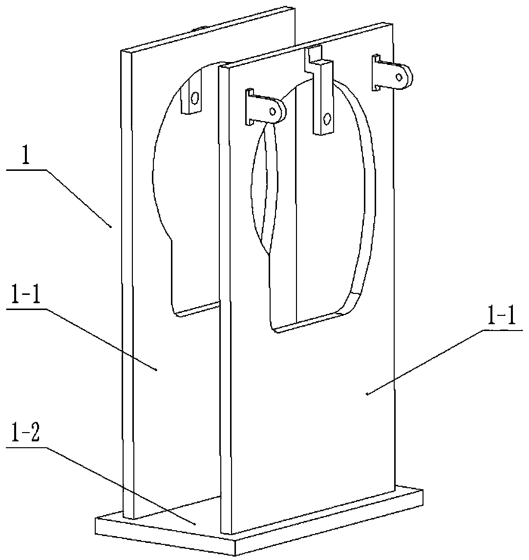
[0032] Combine below Figure 1-11 This embodiment will be described, and this embodiment will further describe Embodiment 1. The frame 1 includes a side plate 1-1 and a bottom plate 1-2, and the bottom plate 1-2 is fixedly connected with two opposite side plates 1 -1, the side plate 1-1 is provided with a semicircular groove 1-1-1, a rectangular groove 1-1-2 and a transition arc edge 1-1-3, and the rectangular groove 1-1-2 is located in the semicircular groove The lower end of 1-1-1, the semicircular groove 1-1-1 communicates with the rectangular groove 1-1-2, and the right end of the rectangular groove 1-1-2 and the semicircular groove 1-1-1 is provided with a transition arc Side 1-1-3; when the opening of the mold fixing part 3 faces upwards, the taper sleeve base 3-1 is against the inner side of the semicircular groove 1-1-1, and the spring 4-5 is compressed to the shortest state; the opening of the mold fixing part 3 faces When it is down, the taper sleeve base 3-1 slides...

specific Embodiment approach 3

[0033] Combine below Figure 1-11 Describe this embodiment, this embodiment will further explain the second embodiment, the worm gear assembly 2 includes a rectangular shaft 2-1, a circular shaft end 2-2 and a worm wheel 2-3, the two sides of the rectangular shaft 2-1 Both ends are fixedly connected with a circular shaft end 2-2, the worm gear 2-3 is fixedly connected to the right-hand circular shaft end 2-2, and the two circular shaft ends 2-2 are respectively connected to the side plate 1- 1, the rectangular shaft 2-1 is located in the semicircular groove 1-1-1, and the rectangular shaft 2-1 is used to drive the taper sleeve base 3-1 and.


PUM


Abstract

The invention relates to the technical field of magnetic material processing, in particular to a demoulding device and demoulding method of a magnetic material. The demoulding device comprises a rack,a worm gear assembly, a die fixing piece, a push device and a worm assembly, wherein the worm gear assembly is rotatably connected to the rack, the die fixing piece is arranged at an intermediate endof the worm gear assembly, the push device is fixedly connected to the worm gear assembly, the push device elastically pushes the die fixing piece, the die fixing piece is connected to the rack in asliding way, the worm assembly is rotatably connected to the rack, and the worm assembly and the worm gear assembly are engaged and connected by a worm gear. By the demoulding device, dies at different sizes and in different shapes can be rapidly clamped, locking of the die fixing piece can be achieved, so that die installation and processing are facilitated; and the die fixing piece with a downward opening can be pushed to rapidly slide along the rack by the push device, and demoulding is achieved by means of inertia and vibration of a magnetic material when the die fixing piece stops abruptly.

Description

technical field [0001] The invention relates to the technical field of magnetic material processing, in particular to a magnetic material demoulding device and a demoulding method. Background technique [0002] For example, the patent application number is CN201410775091.6, a kind of delayed demoulding mold and demoulding method, including a patrix and a lower mold assembly, a cavity is arranged in the upper mold, and a core is provided on the lower mold assembly: The lower mold assembly includes a lower mold and a stripper plate; the stripper plate is located between the lower mold and the upper mold, and the core fixed on the lower mold passes through the through hole on the stripper plate to cooperate with the cavity; The guide post passes through the through hole on the stripping plate, and slides and fits with the corresponding hole on the upper mold; a first sliding mechanism is arranged between the lower mold and the stripping plate, and the sliding mechanism enables ...

Claims


Application Information

Patent Timeline
Patent Type & Authority Applications(China)
IPC IPC(8): H01F41/02
CPCH01F41/0246
Inventor 金德月
Owner ZHEJIANG NANCI IND CO LTD
Why Eureka
Try Eureka