
Solid waste landfilling method

A solid waste and waste technology, applied in the direction of solid waste removal, landfill technology, etc., can solve the problems of squeezing and breaking the anti-seepage membrane, rupture of the anti-seepage membrane, and threats to the life and health of operators, so as to ensure the safety of landfills. , to ensure the effect of the ecological environment

Active Publication Date: 2018-10-09
镇江新区固废处置股份有限公司
View PDF6 Cites 2 Cited by
  • Summary
  • Abstract
  • Description
  • Claims
  • Application Information

AI Technical Summary

Problems solved by technology

[0002] Solid waste landfill technology began in the 1960s and is one of the ideal treatment methods for the final treatment of solid waste. It is a disposal technology developed from traditional waste stacking and landfill technology. The advantages of less investment, large capacity, and quick results. In the prior art, during the solid waste landfill process, motor vehicles are often used to transport the solid waste to the landfill site. During the transportation process, due to road bumps and other reasons, it is easy to cause waste inside the waste. The anti-seepage film on the surface and the surface layer is broken, and the waste is thrown along the road with the driving of the motor vehicle, which not only endangers the road environment and vegetation environment along the way, but also poses a serious threat to the life and health of the on-site operators. During the operation process, there is a lack of curing agent, and no layered landfill operation is adopted. As a result, the waste materials after landfill are exposed to wind and rain for a period of time, and the internal extrusion deformation is caused. In severe cases, the outer anti-seepage membrane is even broken, causing pollution The surrounding vegetation and ecological environment threaten human water use and pose a threat to human health

Method used


Image

  • Solid waste landfilling method

Examples


Embodiment Construction

[0037] The present invention is described in further detail now in conjunction with accompanying drawing. These drawings are all simplified schematic diagrams, and only illustrate the basic structure of the present invention in a schematic manner, so they only show the configurations related to the present invention.

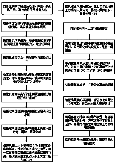
[0038] Such as figure 1 Shown, a kind of landfill method for solid waste, comprises the steps:

[0039] (1) After the solid waste is pretreated, put aside, and the surface is air-dried in sequence, wait for good weather to prepare to enter the site, so as to avoid inconvenient operation for staff in rainy and snowy weather, and at the same time prevent rain and snow from entering the waste during the landfill process and affecting the curing effect;

[0040] (2) Use slag-filled woven bags as the bottom layer on the driving road in the area to be landfilled. The woven bags are arranged in at least two layers, so the source is convenient and cheap, and the protec...


PUM


Abstract

The invention relates to a solid waste landfilling method. Through paving the driving rod surface of a to-be-landfilled area, the waste safety during the transporting process is ensured; in addition,after transporting the waste, an unloading site and a motor vehicle are timely cleaned to ensure the transporting safety; and moreover, layered landfilling operation is adopted to ensure landfilling safety of the interior waste, so that the surrounding vegetation and ecological environment are ensured, and the human water and human health and safety are also ensured.

Description

technical field [0001] The invention relates to a solid waste landfill method, in particular to a solid waste landfill method. Background technique [0002] Solid waste landfill technology began in the 1960s and is one of the ideal treatment methods for the final treatment of solid waste. It is a disposal technology developed from traditional waste stacking and landfill technology. The advantages of less investment, large capacity, and quick results. In the prior art, during the solid waste landfill process, motor vehicles are often used to transport the solid waste to the landfill site. During the transportation process, due to road bumps and other reasons, it is easy to cause waste inside the waste. The anti-seepage film on the surface and the surface layer is broken, and the waste is thrown along the road with the driving of the motor vehicle, which not only endangers the road environment and vegetation environment along the way, but also poses a serious threat to the lif...

Claims


Application Information

Patent Timeline
IPC IPC(8): B09B1/00
CPCB09B1/00Y02W30/30
Inventor 陈翔王双春吴飞朱蜜孙伟国张勋
Owner 镇江新区固废处置股份有限公司
Learn More