Overhung adjusting device of emptying opening of receptacle trough

A technology of adjusting device and material receiving trough, which is applied in the direction of packaging, transportation, packaging, containers, etc. It can solve the problems of long processing time, blockage of the discharge port, and uncontrollable discharge volume, etc., and achieves low installation space requirements, The effect of simple and reliable structure and low maintenance cost

Pending Publication Date: 2018-10-09
SHANDONG IRON & STEEL CO LTD
View PDF7 Cites 0 Cited by
  • Summary
  • Abstract
  • Description
  • Claims
  • Application Information

AI Technical Summary

Problems solved by technology

However, when receiving and unloading bulk materials, large materials or entrained debris are likely to form blockages at the discharge port at the bottom of the receiving tank
Metal receiving troughs can deal with the blockage of the discharge opening of the receiving trough by installing a vibrator on the silo wall, while for concrete receiving troughs, when the discharge opening is dredged, the bottom chute is usually removed for dredging. Long processing times and downtime required
In addition, the bottom of the receiving trough is generally equipped with a discharge gate to adjust the discharge volume, but due to the limited space at the bottom of some receiving troughs, it is impossible to install gates and other devices, and the discharge volume cannot be controlled

Method used


Image

  • Overhung adjusting device of emptying opening of receptacle trough
  • Overhung adjusting device of emptying opening of receptacle trough
  • Overhung adjusting device of emptying opening of receptacle trough

Examples


Embodiment Construction

[0022] In order to make the purpose, technical solution and advantages of the present invention clearer, the technical solution of the present invention will be clearly and completely described below in conjunction with specific embodiments of the present invention and corresponding drawings. Apparently, the described embodiments are only some of the embodiments of the present invention, but not all of them. Based on the embodiments of the present invention, all other embodiments obtained by persons of ordinary skill in the art without making creative efforts fall within the protection scope of the present invention.

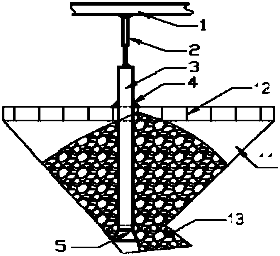
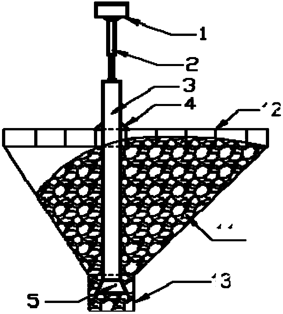
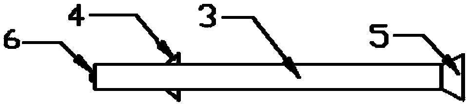
[0023] like figure 1 , 2 As shown in and 3, the hanging adjustment device of the discharge port of the receiving trough of the present invention is arranged on the receiving trough 11, and the top of the receiving trough 11 is provided with a grid 12 for preventing debris from being blocked. The bottom of the trough 11 is provided with a discharge port 13 for ...


PUM


Abstract

The invention relates to an overhung adjusting device of an emptying opening of a receptacle trough. The adjusting device is arranged on the receptacle trough, a grid is arranged on the top of the receptacle trough, and the emptying opening is formed in the bottom of the receptacle trough. The device comprises a fixed beam, a power device and an adjusting rod, wherein the fixed beam is fixed to the receptacle trough; one end of the power device is overhung on the fixed beam while the other end of the power device is connected to an adjusting rod; the adjusting rod is of an overhung structure,the top end of the adjusting rod is connected to the power device, the overhung part of the adjusting rod is inserted into the receptacle trough through the grid, an adjusting block is arranged at thebottom end of the adjusting rod, and the adjusting block is aligned to the emptying opening and stretches into the emptying opening. By means of the device, the spatial dimension of the emptying opening is changed by adjusting the position of the adjusting block up and down, and meanwhile, a material moves downward, so that blockage of the emptying opening of the receptacle trough can be dredge quickly; the spatial dimension of the emptying opening is changed by adjusting the position of the adjusting block up and down, so that the emptying amount of the emptying opening of the receptacle trough can be adjusted simply.

Description

technical field [0001] The invention relates to the field of material conveying equipment, and more particularly relates to a hanging adjustment device for a discharge port of a material receiving chute. Background technique [0002] Receiving troughs are widely used in metallurgy, electric power and other production fields, and are an important material transfer method. There is generally a grille on the top of the receiving trough to prevent debris from clogging. However, when receiving and unloading bulky materials, bulky materials or entrained sundries are likely to form blockages at the discharge port at the bottom of the receiving tank. Metal receiving troughs can deal with the blockage of the discharge opening of the receiving trough by installing a vibrator on the silo wall, while for concrete receiving troughs, when the discharge opening is dredged, the bottom chute is usually removed for dredging. Longer processing times and required downtime for the job. In add...

Claims


Application Information

Patent Timeline
Patent Type & Authority Applications(China)
IPC IPC(8): B65D88/64
CPCB65D88/64
Inventor 吴启瑞王学军
Owner SHANDONG IRON & STEEL CO LTD
Why Eureka
Try Eureka