Supercharge Your Innovation With Domain-Expert AI Agents!

Reason analysis method for commutation failure of DC transmission system

A technology for DC transmission system and commutation failure, applied in power transmission AC network, detecting faults by conductor type, fault location, etc., can solve the problem of voltage amplitude drop, unbalanced distribution of energy resources and load centers, and no AC system Synchronization and other issues to achieve the effect of operating stability

Inactive Publication Date: 2018-10-09
ELECTRIC POWER RES INST OF STATE GRID ZHEJIANG ELECTRIC POWER COMAPNY +2
View PDF4 Cites 6 Cited by
  • Summary
  • Abstract
  • Description
  • Claims
  • Application Information

AI Technical Summary

Problems solved by technology

[0002] The successful application of the AC-DC hybrid system can effectively alleviate the unbalanced distribution of energy resources and load centers in my country. At the same time, there is no synchronization problem of the AC system connection, which improves the safety of the power grid operation. However, the DC transmission project also faces some unavoidable questions
[0003] The commutation failure of the converter is a very common type of fault, which brings unpredictable damage and impact to the DC transmission system and the AC transmission system on both sides
Existing studies are relatively one-sided in the analysis of the causes of commutation failure, or simply analyze factors such as voltage amplitude drop and phase shift, or ignore the cause analysis and focus on the simulation research of control strategies, or directly analyze the multi-drop transmission system. mutual influence

Method used


Image

  • Reason analysis method for commutation failure of DC transmission system
  • Reason analysis method for commutation failure of DC transmission system
  • Reason analysis method for commutation failure of DC transmission system

Examples


Embodiment Construction

[0030] The present invention will be further described below in conjunction with the accompanying drawings and specific embodiments.

[0031] 1. Reason analysis method

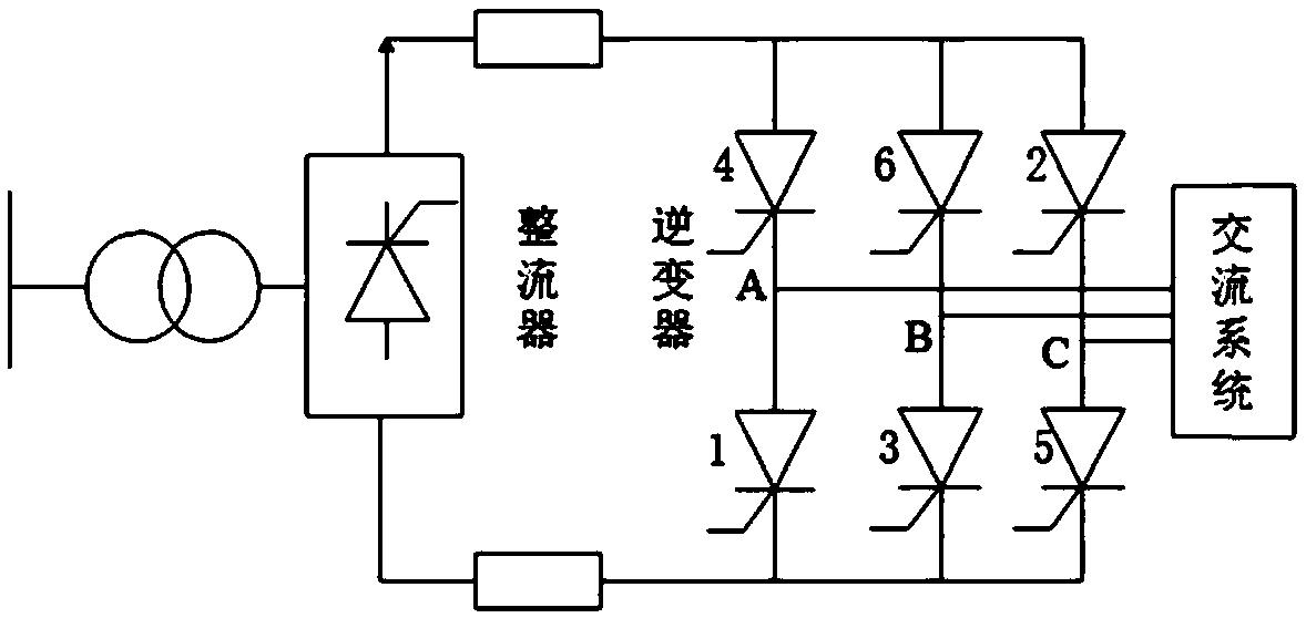
[0032] Such as figure 1 As shown in the working structure diagram of the converter, the present invention divides the commutation failure process in the AC-DC hybrid system into different stages, and analyzes the main causes of the commutation failure in different stages. Including the following steps:

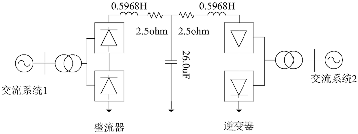
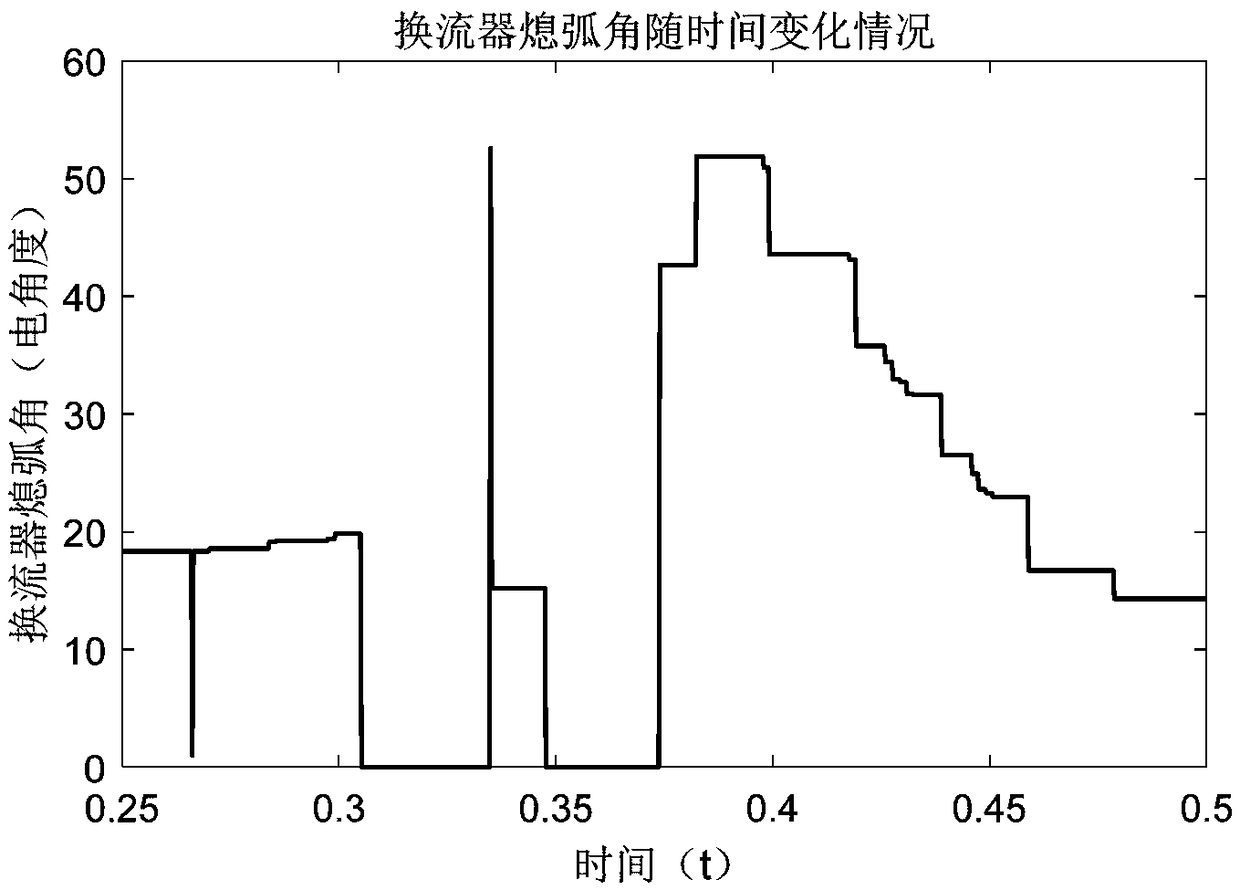
[0033] (1) The present invention takes the simplest single-bridge converter as an example, and explains the reasons for commutation failure in a direct current transmission system from the principle of thyristor commutation. Establish the 500kV, 1000MW DC transmission CIGRE international standardized model in PSCAD software. Set different electrical faults at the outlet of the AC bus on the inverter side, and cut them off after the same duration. The change of arc extinguishing angle is used as the judgmen...


PUM


Abstract

The invention discloses a reason analysis method for a commutation failure of a DC transmission system. An existing research has the disadvantages as follows: analysis of the reason of the commutationfailure is relatively one-sided, or the factors, such as voltage amplitude drop and phase shift are simply analyzed, or the condition that reason analysis focuses on a simulation research of a control strategy or the interaction between multi-drop transmission systems is directly analyzed. According to the reason analysis method, the defects that existing analysis of the reason of the commutationfailure is incomplete and single-stage analysis is relatively one-sided are overcome, for example, the defects that occurrence of a secondary commutation failure cannot be considered and the influences of a harmonic wave and DC magnetic bias of a converter transformer are neglected are also overcome. According to the reason analysis method, the commutation failure process in an AC / DC hybrid system is divided into two different stages and the main reason of the commutation failure is analyzed at different stages, so that the operation stability of an interconnected AC / DC system is achieved when the interconnected AC / DC system is in a failure.

Description

technical field [0001] The invention belongs to the field of direct current transmission system operation and control, in particular to a method for analyzing the cause of phase commutation failure of the direct current transmission system. Background technique [0002] The successful application of the AC-DC hybrid system can effectively alleviate the unbalanced distribution of energy resources and load centers in my country. At the same time, there is no synchronization problem of the AC system connection, which improves the safety of the power grid operation. However, the DC transmission project also faces Some unavoidable questions. [0003] The commutation failure of the converter is a very common type of fault, which brings unpredictable damage and impact to the DC transmission system and the AC transmission system on both sides. Existing studies are relatively one-sided in the analysis of the causes of commutation failure, or simply analyze factors such as voltage amp...

Claims


Application Information

Patent Timeline
IPC IPC(8): H02J3/36G01R31/08
CPCG01R31/086H02J3/36Y02E60/60
Inventor 李继红楼伯良许多陆承宇宣晓华黄弘扬马俊超华文彭琰赵一琰王龙飞吴跨宇吴峰史林军
Owner ELECTRIC POWER RES INST OF STATE GRID ZHEJIANG ELECTRIC POWER COMAPNY
Features
  • R&D
  • Intellectual Property
  • Life Sciences
  • Materials
  • Tech Scout
  • Unparalleled Data Quality
  • Higher Quality Content
  • 60% Fewer Hallucinations
Learn More