Motor
A yoke and tooth technology, applied in the field of motors, can solve the problems of inconvenient maintenance, inconvenient operation, and low winding efficiency of a wire embedding machine, and achieve the effects of convenient disassembly, maintenance and assembly.
- Summary
- Abstract
- Description
- Claims
- Application Information
AI Technical Summary
Problems solved by technology
Method used
Image

Examples
Embodiment 1
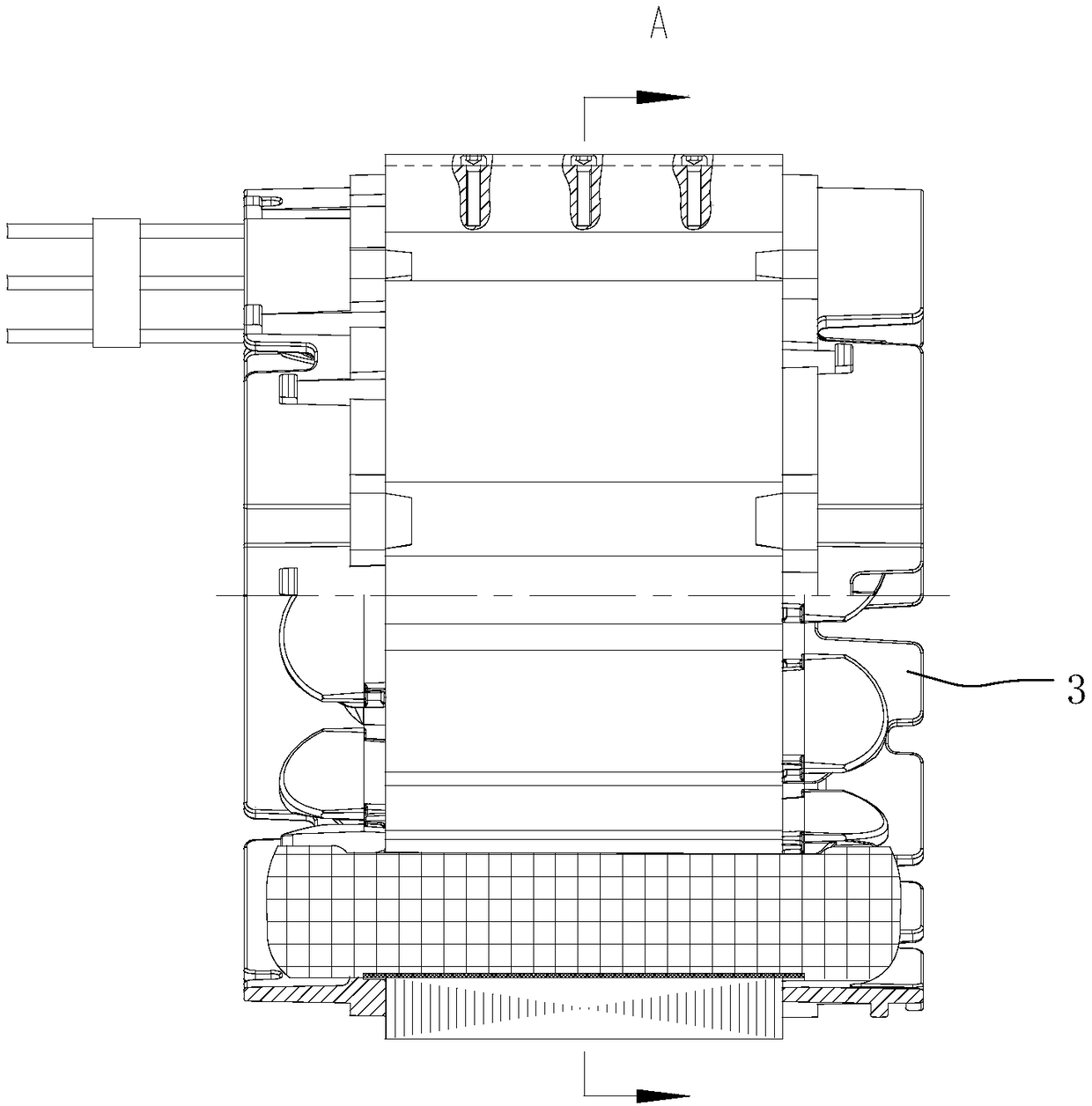
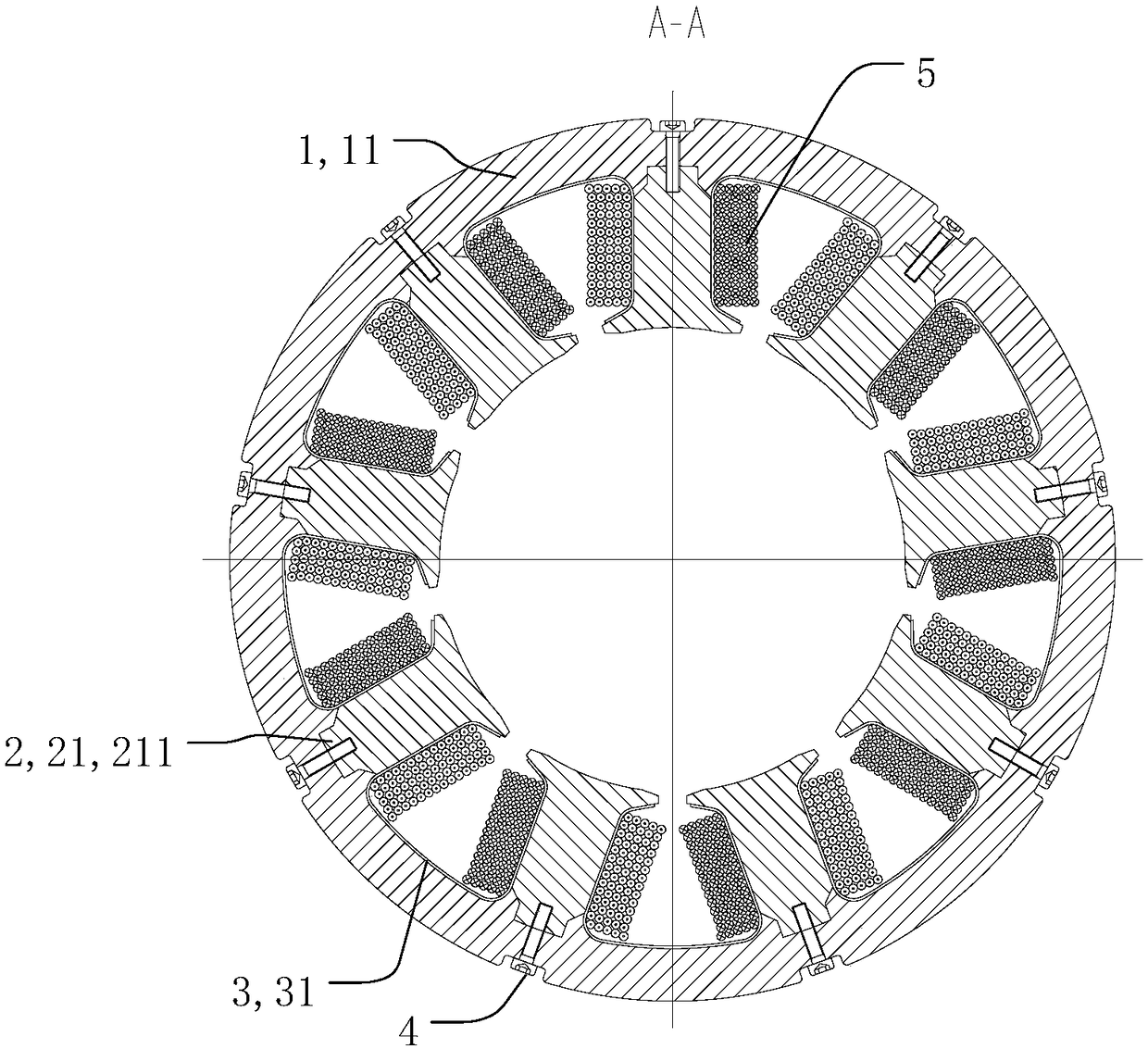
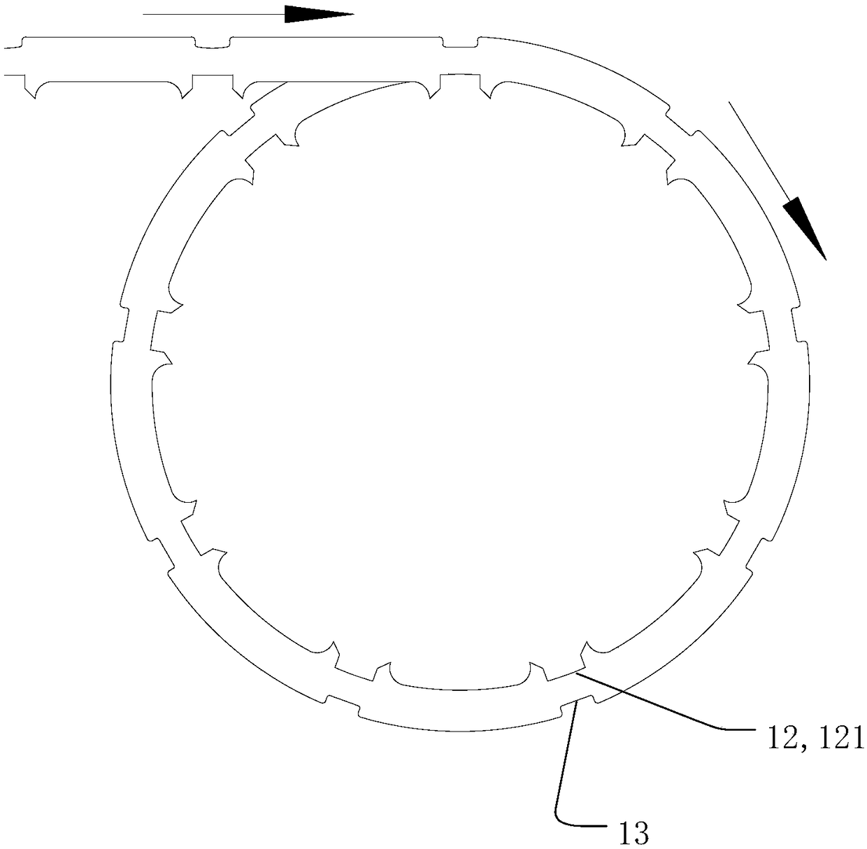
[0052] Such as Figure 4 As shown, the skeleton unit 31 has an integral structure, the tooth part 2 and the yoke part 1 are detachably connected, and the tooth part 2 passes through the inner hole of the skeleton unit 31 to form a tooth part assembly. In the tooth assembly, the positioning portion 211 of the tooth portion 2 protrudes from the tubular structure 311 of the skeleton unit 31, and the tooth assembly inserts the positioning portion 211 into the groove 121 of the yoke 1 Position the tooth part assembly on the yoke part 1, and then connect the tooth part 2 and the yoke part 1 through a fastener 4, so that the tooth part 2 is connected to the yoke part 1 .
[0053] In this embodiment, the tooth part 2 in the tooth part assembly is installed on the winding equipment, and the winding 5 is completed by the rotation of the tooth part assembly. In this way, the wire inserting machine can be omitted, and the winding for distributed winding can be used directly. The thread ...
Embodiment 2
[0055] Such as Figure 5-Figure 8 As shown, the skeleton unit 31 is a split structure, the skeleton unit 31 includes a first part 32 and a second part 33, and the first part 32 and the second part 33 are along the axial direction of the yoke 1 The skeleton unit 3 in the first embodiment is divided into two parts, and the two parts are butted to form a skeleton unit 31. At this time, the yoke 1 and the tooth 2 can be integrally formed or detachably connected. The frame unit 31 can insert the first part 32 and the second part 33 into the tooth part from both ends of the tooth part 2 after the yoke part 1 and the tooth part 2 are connected. 2, of course, the first part 32 and the second part 33 can also be assembled into the skeleton unit 31 first, and then the skeleton unit 31 and the tooth part 2 can be assembled into the tooth part assembly, Finally, the tooth assembly is connected with the yoke 1 .
Embodiment 3
[0057] Such as Figure 9 and Figure 10 As shown, the skeleton unit 31 is a split structure, the skeleton unit 31 includes a third part 34 and a fourth part 35, the third part 34 and the fourth part 35 are along the yoke 1 Divide the skeleton unit in the first embodiment radially into two parts close to and away from the yoke 1, at this time, the teeth 2 and the yoke 1 are detachably connected, preferably, the third The part 34 and the fourth part 35 are assembled into the skeleton unit 31, and then the skeleton unit 31 and the tooth part 2 are assembled into a tooth part assembly, and finally the tooth part assembly is connected to the yoke part 1 .
[0058] In this embodiment, the winding 5 can be wound directly through a mold, and then dipped in paint to shape, and then the winding 5 is passed on the fourth part 35, and then the third part 34 and the fourth part 35 are assembled into the described Skeleton unit 31.
PUM
 Abstract
Description
Claims
Application Information
 - Generate Ideas
- Intellectual Property
- Life Sciences
- Materials
- Tech Scout
- Unparalleled Data Quality
- Higher Quality Content
- 60% Fewer Hallucinations
Browse by: Latest US Patents, China's latest patents, Technical Efficacy Thesaurus, Application Domain, Technology Topic, Popular Technical Reports.
© 2025 PatSnap. All rights reserved.Legal|Privacy policy|Modern Slavery Act Transparency Statement|Sitemap|About US| Contact US: help@patsnap.com