
Internet of things low-power radio frequency circuit and terminal

A technology of IoT terminals and circuits, applied in electrical components, transmission systems, etc., can solve problems affecting the signal-to-noise ratio of useful signals, reduce receiver sensitivity, etc., achieve good filtering effect, reduce secondary reflection signals from entering the chip, The effect of enhancing sensitivity

Active Publication Date: 2020-11-27
SHENZHEN SHENGLU IOT COMM TECH CO LTD
View PDF10 Cites 0 Cited by
  • Summary
  • Abstract
  • Description
  • Claims
  • Application Information

AI Technical Summary

Problems solved by technology

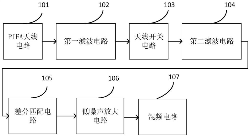
In the existing radio frequency circuit of the Internet of Things, when receiving the radio frequency signal, it is easy to generate a reflected signal from the interior of the Internet of Things chip through the radio frequency circuit, and after the reflection occurs again, it will be transmitted along the radio frequency circuit receiving circuit to the inside of the chip. When the reflected signal will seriously affect the signal-to-noise ratio of the useful signal, thereby reducing the sensitivity of the receiver

Method used


Image

  • Internet of things low-power radio frequency circuit and terminal
  • Internet of things low-power radio frequency circuit and terminal
  • Internet of things low-power radio frequency circuit and terminal

Examples


Embodiment Construction

[0033] The technical solutions in the embodiments of the present invention will be clearly and completely described below in conjunction with the accompanying drawings in the embodiments of the present invention. Obviously, the described embodiments are only part of the embodiments of the present invention, not all of them. Based on the implementation manners in the present invention, all other implementation manners obtained by persons of ordinary skill in the art without making creative efforts belong to the scope of protection of the present invention.

[0034] The terms "first", "second" and the like in the description and claims of the present invention and the above drawings are used to distinguish different objects, rather than to describe a specific order. Furthermore, the terms "include" and "have", as well as any variations thereof, are intended to cover a non-exclusive inclusion. For example, a process, method, system, product or device comprising a series of steps ...


PUM


Abstract

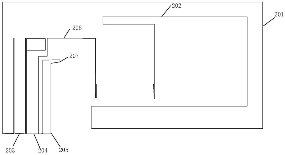
The embodiments of the invention disclose a signal processing circuit, which is applied to an Internet of Things terminal. The Internet of Things terminal comprises a main board. The circuit comprises: a PIFA antenna, a first filter circuit, an antenna switch circuit, a second filter circuit, a differential matching circuit, a low noise amplifying circuit and a mixing circuit; the PIFA antenna comprises an outer strip wire, a radiator, a grounding bending wire, a feeding plate, a grounding point and a short-circuit probe, the outer strip wire encircles a rectangle with an opening, the openingis located at the outer strip wire and the grounding point, the radiator is arranged inside the rectangle and connected to the grounding bending wire, the grounding bending wire is connected to the grounding point, the end of the grounding bending wire is connected to the short-circuit probe, and the feeding plate is arranged between the grounding point and the outer strip wire. By serially connecting the surface acoustic filter, the differential matching circuit and the low noise amplifier, secondary reflection signals can be reduced to enter the inside of a chip, so that the signal-to-noiseratio of useful signals is improved, and the sensitivity of a receiver is enhanced.

Description

technical field [0001] The invention relates to the technical field of circuit structures, in particular to an Internet of Things low-power radio frequency circuit and a terminal. Background technique [0002] With the rapid development of the Internet of Things technology, various terminal products of the Internet of Things have been gradually popularized in daily life and applied in all aspects of life, bringing great convenience to daily life. In the existing radio frequency circuit of the Internet of Things, when receiving the radio frequency signal, it is easy to generate a reflected signal from the interior of the Internet of Things chip through the radio frequency circuit, and after the reflection occurs again, it will be transmitted along the radio frequency circuit receiving circuit to the inside of the chip. At this time, the reflected signal will seriously affect the signal-to-noise ratio of the useful signal, thereby reducing the sensitivity of the receiver. Co...

Claims


Application Information

Patent Timeline
Patent Type & Authority Patents(China)
IPC IPC(8): H04B1/10H04B1/40
CPCH04B1/10H04B1/1027H04B1/40H04B2001/1054
Inventor 杜光东
Owner SHENZHEN SHENGLU IOT COMM TECH CO LTD
Learn More