Wiped film evaporator

A wiped film evaporator and evaporation cylinder technology, applied in evaporator accessories, evaporation, chemical instruments and methods, etc., can solve the problems of uneven heating and easy drying of wiped film evaporators, and improve evaporation efficiency and production capacity. Uniform distribution of materials and the effect of preventing coking

Pending Publication Date: 2018-10-12
邵伟科
View PDF9 Cites 3 Cited by
  • Summary
  • Abstract
  • Description
  • Claims
  • Application Information

AI Technical Summary

Problems solved by technology

[0010] The purpose of the present invention is to provide a wiped film evaporator with uniform heating, shorter material residence time, high evaporation intensity and preventing coking in view of the defects of uneven heating and easy drying of the existing wiped film evaporator

Method used


Image

  • Wiped film evaporator
  • Wiped film evaporator

Examples


Embodiment 1

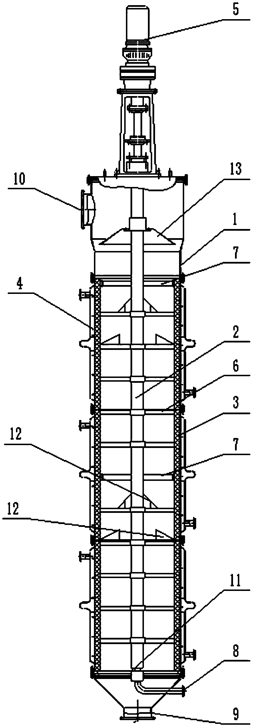
[0027] Such as figure 1 As shown, a wiped film evaporator includes an evaporation cylinder 1 , a drive shaft 2 and a scraper 3 . The evaporation cylinder 1 has a plurality of heat medium jackets 4 sequentially from top to bottom. The transmission shaft 2 is driven to rotate by the motor 5 and is arranged in the evaporation cylinder 1 . The scraper 3 is connected to the transmission shaft 2 through a plurality of scraper supports 6 . Two feed distributors 7 are arranged on the transmission shaft 2, and the transmission shaft 2 and the two feed distributors 7 arranged at intervals are hollow and communicate with each other. The materials pass through the cavity of the transmission shaft 2 and the feed distributor 7, Spray from one end of the feed distributor 7 to the inner wall of the evaporation cylinder 1 . Both the material inlet 8 and the material outlet 9 are located at the lower part of the evaporation cylinder 1 , and the upper part of the evaporation cylinder 1 has a ...

Embodiment 2

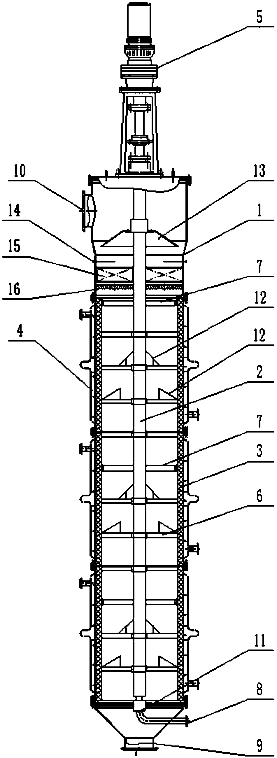
[0029] Such as figure 2 As shown, a wiped film evaporator includes an evaporation cylinder 1 , a drive shaft 2 and a scraper 3 . The evaporation cylinder 1 has a plurality of heat medium jackets 4 sequentially from top to bottom. The transmission shaft 2 is driven to rotate by the motor 2 and is arranged in the evaporation cylinder 1 . The scraper 3 is connected to the transmission shaft 2 through a plurality of scraper supports 6 . Three feed distributors 7 are arranged on the transmission shaft 2, the transmission shaft 2 and the three feed distributors 7 arranged at intervals are hollow and communicate with each other, and the materials pass through the cavity of the transmission shaft 2 and the feed distributor 7, One end of the feed distributor 7 is sprayed toward the inner wall of the evaporation cylinder 1 . Both the material inlet 8 and the material outlet 9 are located at the lower part of the evaporation cylinder 1 , and the upper part of the evaporation cylinder...


PUM


Abstract

A wiped film evaporator comprises an evaporation cylinder, a drive shaft arranged in the evaporation cylinder and driven by a motor to rotate as well as a scraper connected onto the drive shaft through a scraper support, wherein a plurality of feed distributors are arranged on the drive shaft; the drive shaft and the feed distributors are hollow and mutually communicated; materials are sprayed from one ends of the feed distributors to the inner wall of the evaporation cylinder through cavities of the drive shaft and the feed distributors. The hollow drive shaft and feed distributors are takenas material channels for the materials, the materials are sprayed from different positions of the evaporation cylinder, so that the materials are no longer centralized at the upper part of the evaporation cylinder and are distributed more uniformly, retention time of the materials is effectively shorter, and coking is prevented. Heating medium jackets in different positions correspond to materialspray ports in the different positions respectively, so that load of the heating medium jackets is more uniform, uniformity of temperature in the different positions of the evaporation cylinder is guaranteed, energy consumption is reduced effectively, and evaporation efficiency and production capacity of the evaporator are improved.

Description

technical field [0001] The invention belongs to the technical field of evaporator equipment, and in particular relates to a wiped-film evaporator which receives heat uniformly, has high evaporation intensity and prevents coking. Background technique [0002] The full name of the thin film evaporator is a mechanically stirred thin film evaporator, also known as a rotary thin film evaporator. It is a new type of high-efficiency energy-saving falling film evaporator. It is widely used in chlor-alkali, chemical, light industry, food, pharmaceutical and environmental protection industries due to its superior performance such as high heat transfer coefficient of equipment, short material residence time, wide applicable viscosity range and large operating flexibility. [0003] Its working principle is as follows: After the material enters the evaporator, it is forced to form a film by the agitation of the scraper on the rotor. The heat of the heat source exchanges heat with the ma...

Claims


Application Information

Patent Timeline
Patent Type & Authority Applications(China)
IPC IPC(8): B01D1/22B01D1/30
CPCB01D1/22B01D1/30
Inventor 邵伟科
Owner 邵伟科
Why Eureka
Try Eureka