
A kind of bending method of thin-walled ring profile

A technology of bending and ring parts, which is applied in the field of thin-walled ring parts bending, can solve the problems of inability to accurately determine the bending position, effort, manual operation errors, etc., and achieve the effect of convenient blanking process, smooth movement and reduced labor load

Active Publication Date: 2019-09-24
NANTONG GUANGYI ELECTROMECHANICAL CO LTD
View PDF5 Cites 0 Cited by
  • Summary
  • Abstract
  • Description
  • Claims
  • Application Information

AI Technical Summary

Problems solved by technology

[0002] In the bending of the workpiece, at present, the manual feeding and bending of the workpiece is mainly carried out, which is laborious, and the bending position cannot be accurately determined, and there is a certain error in manual operation; the bending machine places the workpiece on the turntable, and the supporting pin is fixed on the On the machine tool, the central pin and the bending pin are installed on the working disc, and the workpiece is bent when the disc rotates; in order to bend workpieces of various diameters, there are several holes on the working disc for inserting the bending pins Shaft, you can also replace the center pin shaft with different diameters accordingly

Method used


Image

  • A kind of bending method of thin-walled ring profile
  • A kind of bending method of thin-walled ring profile
  • A kind of bending method of thin-walled ring profile

Examples


Embodiment Construction

[0031] In order to make the technical means, creative features, goals and effects achieved by the present invention easy to understand, the present invention will be further described below in conjunction with specific embodiments.

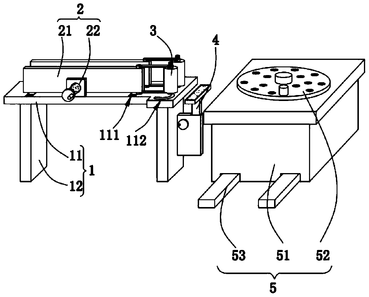
[0032] Such as Figure 1-Figure 5 As shown, a thin-walled ring profile bending method according to the present invention comprises the following steps:

[0033] s1: Polish and degrease the plate to be bent;

[0034] s2: Put the plate to be bent in s1 into the bending machine;

[0035] s3: Bending the plate in s2;

[0036] s4: transport the plate in s3 to the next process;

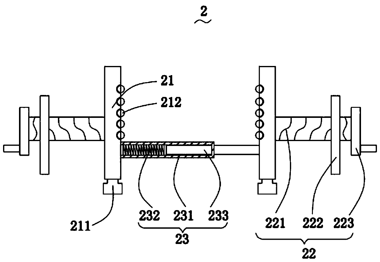
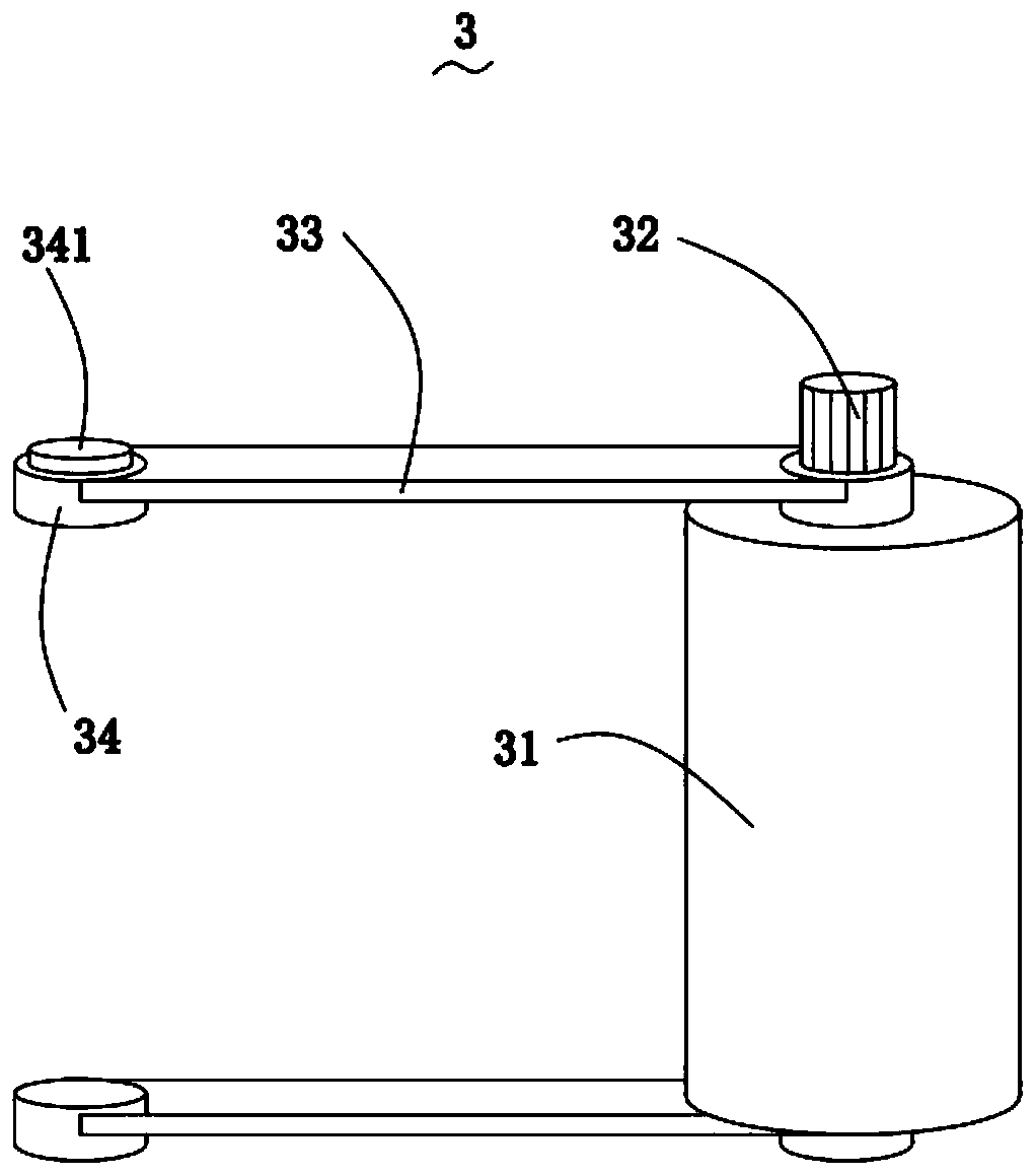
[0037] Wherein, the bending machine adopted in this method includes a supporting mechanism 1, a clamping mechanism 2, a conveying mechanism 3, a lifting mechanism 4 and a processing mechanism 5; the top of the supporting mechanism 1 is slidably connected with the clamping mechanism 2, so The clamping mechanism 2 is used to clamp and limit the workpiece; one end of the clamp...


PUM


Abstract

The invention relates to the technical field of structural component bending, in particular to a thin-wall ring sectional material bending method. A bending machine adopted by the method comprises a supporting mechanism, a clamping mechanism, conveying mechanisms, a lifting mechanism and a machining mechanism. Sectional materials can be limited and clamped through clamping plates and can be placedon an object placing mechanism, so that the sectional materials are not required to be handheld so as to be bent and machined through manual work, and the labor capacity of a worker is reduced effectively; a space between the clamping plates can be regulated according to the widths of the sectional materials, and the object placing mechanism can make stretching motion when the space between the clamping plates is changed, so that the clamping mechanism is wider in application scope; the motion of the sectional materials is more fluent through balls distributed on the inner walls of the clamping plates; and the conveying mechanisms are rotationally connected with the clamping mechanism, so that a space between the two conveying mechanisms can be regulated according to the widths of the sectional materials, and automatic conveying is achieved.

Description

technical field [0001] The invention relates to the technical field of structural component bending, in particular to a thin-walled ring component bending method. Background technique [0002] In the bending of the workpiece, at present, the manual feeding and bending of the workpiece is mainly carried out, which is laborious, and the bending position cannot be accurately determined, and there is a certain error in manual operation; the bending machine places the workpiece on the turntable, and the supporting pin is fixed on the On the machine tool, the central pin and the bending pin are installed on the working disc, and the workpiece is bent when the disc rotates; in order to bend workpieces of various diameters, there are several holes on the working disc for inserting the bending pins The shaft can also be replaced with a center pin shaft of a different diameter accordingly. In view of this, the present invention provides a thin-walled ring section bar bending method, ...

Claims


Application Information

Patent Timeline
Patent Type & Authority Patents(China)
IPC IPC(8): B21D5/00B21D43/09
Inventor 尹苑苑付志杰
Owner NANTONG GUANGYI ELECTROMECHANICAL CO LTD
Learn More